Mechanism for attenuating torque pulsations between an engine and a rotorcraft rotor driven by the engine

a technology of torque pulsation and rotorcraft, which is applied in the direction of propellers, propulsive elements, water-acting propulsive elements, etc., can solve the problems of rotorcraft torque pulsations that are naturally induced between the drive shaft, fatigue failure of the members making up the transmission system, and excessive torque pulsations. to achieve the effect of restricting the overall radial size of the mechanism and avoiding excessive mechanism siz

Active Publication Date: 2013-11-12
EUROCOPTER
View PDF9 Cites 2 Cited by
  • Summary
  • Abstract
  • Description
  • Claims
  • Application Information

AI Technical Summary

Benefits of technology

[0008]One object of the present invention is to provide a mechanism for attenuating torque pulsations between an engine and a rotorcraft rotor driven in rotation by the engine, the mechanism having a size and weight that make it suitable for use in rotorcraft. It is particularly desirable for such a mechanism to be simple in structure, light in weight, and compact in order to make it acceptable for use in an aircraft, in particular a rotorcraft, that is to be lifted by means of at least one rotor and caused to move through the air. Nevertheless, such a mechanism must be robust so as to be long-lasting in spite of the high levels of torque transmitted between the engine and the rotor. Such a mechanism must also be capable of being easily mounted in the transmission system between the engine and the rotor it drives, and it must make it easy to perform any maintenance operations that might be required, whether on the mechanism itself or on other members making up the transmission system.
[0016]Under the effect of centrifugal force and the force of inertia as induced by the drive shaft being set into rotation, the mass serves to give rise to phase shifts between the inlet shaft and the outlet shaft as a function of the torque pulsations induced by the resistance offered by the driven shaft against being driven in rotation by the drive shaft. These phase shifts are absorbed by the torsion shaft. The force multiplication effect produced by the lever system serves to limit the mass that needs to be used to achieve absorption of given induced torque pulsations. In spite of the small mass used for causing the torsion shaft to twist, it nevertheless compensates the force of the torsion shaft in phase opposition by making use of the lever effect provided by the lever system. As a function of the centrifugal force and the force of inertia induced by setting the drive shaft into rotation, the mass of effect that is amplified by the lever system spontaneously causes torque pulsations to be absorbed. More particularly, the force transmissions induced by the torque pulsations at a given frequency are absorbed while not affecting the transmission of torque between the drive shaft and the driven shaft. Using the lever system makes it possible to reduce the mass for the torsion shaft acting to absorb the torque pulsations, such that there is no need for the mass and the extent of said torsion shaft to be unacceptable for an application in the field of rotorcraft. More particularly, the lever system serves to increase the stiffness of the torsion shaft and consequently to restrict its extension, with the advantage of making it suitable for use in the field of rotorcraft. The radial extent of the lever arm and its pivoting movement about the common axis of the torsion shaft, the inlet shaft, and the outlet shaft, give rise to the mass rocking tangentially relative to said common axis, while avoiding giving rise to unbalance that would affect the equilibrium of the forces involved when driving the rotor.
[0023]In an improved embodiment, the inlet shaft or the outlet shaft that is hinged to the lever arm between its said ends is in hinged connection with said lever arm via a link. This embodiment presents the advantage of avoiding a statically undetermined configuration for the mechanism. The pivoting of the mass and the hinged junction to the corresponding shaft via the link acts under the effect of centrifugal force to obtain greater stiffness for this pivoting and consequently makes it possible to further reduce the overall size of the torsion shaft, in particular in terms of diameter, for given stiffness.
[0036]Between its ends, the lever arm may form an angle lying in the range 90° to 180°. Ideally, in order to avoid making the mechanism excessively large in a radial direction, the lever arm forms a 90° bend between its ends, the corresponding inlet and / or outlet shafts being hinged in the zone of the bend. Taken together, the arrangement of the lever arm with a 90° angle between its ends and a said lever ratio of less than 10 makes it possible to restrict the overall radial size of the mechanism as well as possible.
[0037]The mass is advantageously made up of a plurality of flyweights that are radially uniformly distributed, i.e. circumferentially uniformly distributed about the common coaxial axis along which the inlet, outlet, and torsion shafts extend. These flyweights are individually carried by respective individual lever arms to which the inlet and outlet shafts are hinged. The effect of centrifugal force and of the force of inertia is radially distributed over the inlet and outlet shafts thus making it possible to balance the forces induced on the torsion shaft in order to damp torque pulsations, thereby also serving to avoid unbalance.
[0038]In an elementary embodiment providing both an effect of attenuating torque pulsations and balanced transmission of forces to the torsion shaft, and that is satisfactory for producing a mechanism of small radial size, the flyweights and the individual lever arms are preferably three in number, being radially uniformly distributed at 120° intervals about the common coaxial axis along which the inlet, outlet, and torsion shafts extend.

Problems solved by technology

A general problem occurs that lies in torque pulsations that are naturally induced between the drive shaft and the driven shaft.
Such torque pulsations are particularly large in rotorcraft because of the weight of such aircraft that needs to be compensated in order to lift them and / or move them.
Such torque pulsations transmitted via the transmission system between the engine and the rotor tend to give rise to fatigue failures of the members making up the transmission system.
Such a solution presents the advantage of being simple to implement, but it requires the use of a shaft presenting a length and / or a weight that makes it unacceptable for use in the field of rotorcraft.

Method used


Image

  • Mechanism for attenuating torque pulsations between an engine and a rotorcraft rotor driven by the engine
  • Mechanism for attenuating torque pulsations between an engine and a rotorcraft rotor driven by the engine
  • Mechanism for attenuating torque pulsations between an engine and a rotorcraft rotor driven by the engine

Examples


Embodiment Construction

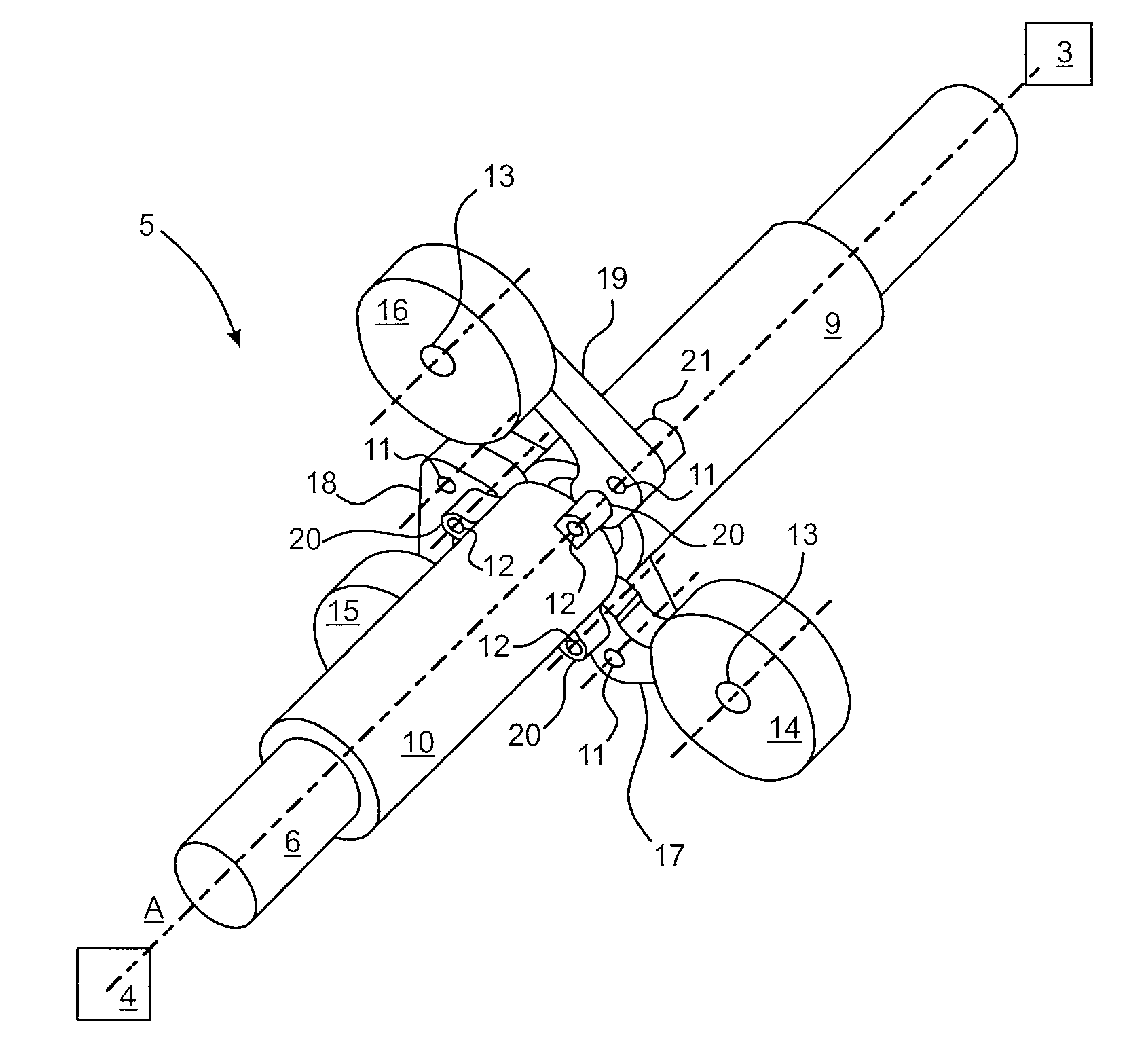
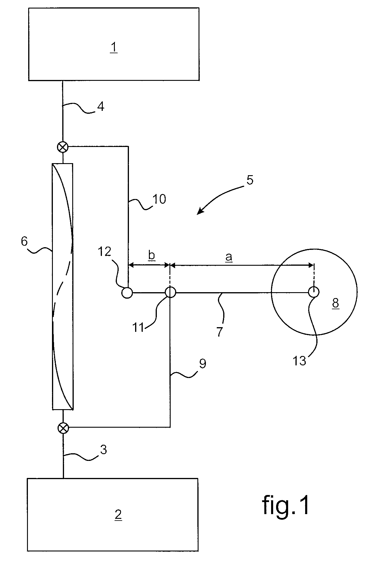
[0044]FIG. 1 shows a mechanism for fitting to a rotorcraft, being interposed between a rotor 1 and an engine 2, in particular a diesel engine, for driving the rotor 1 in rotation. The mechanism is for damping torque pulsations as induced when the rotor 1 is rotated by the engine 2.

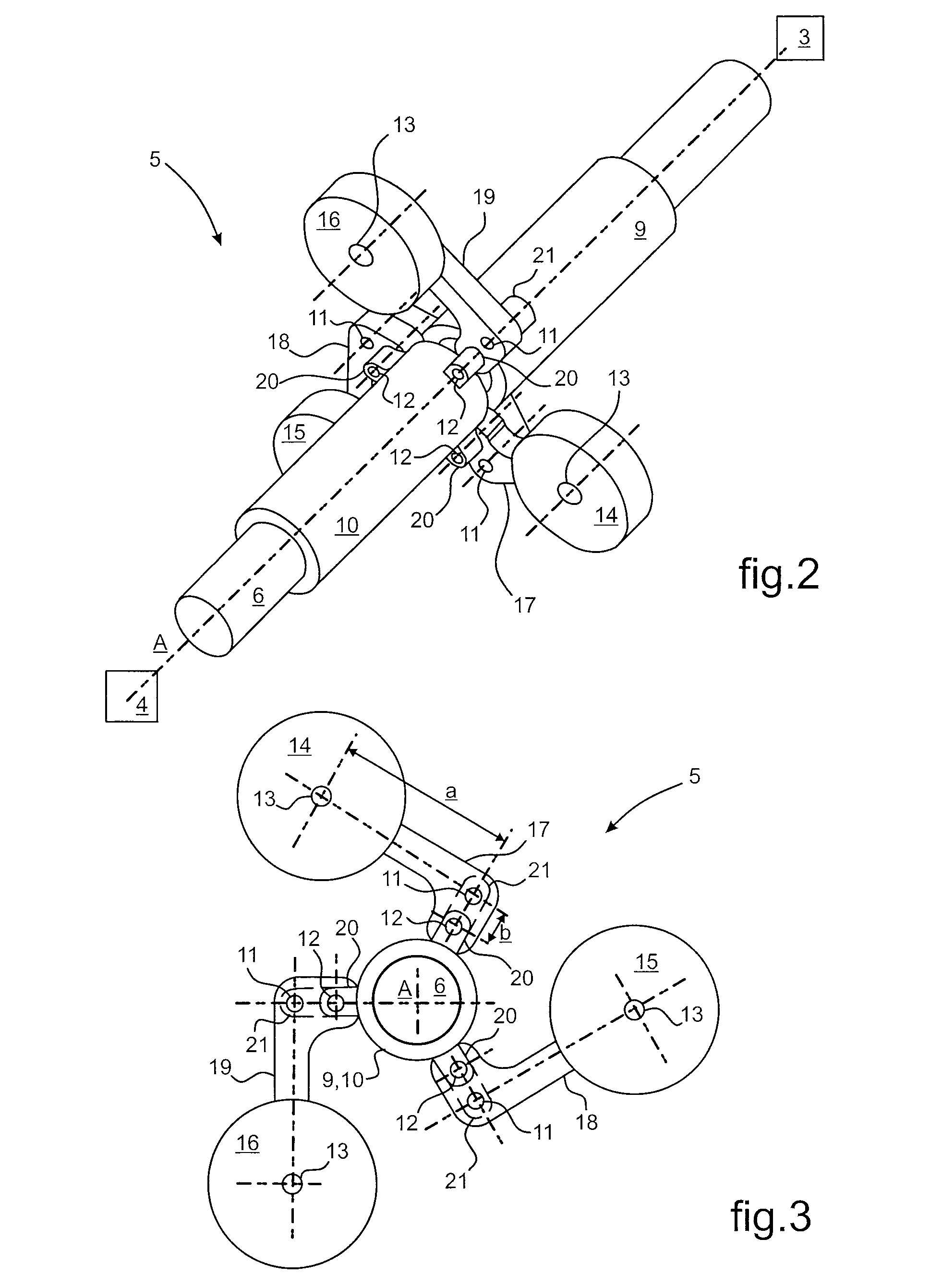
[0045]A drive shaft 3 that is engaged with the engine 2 communicates with a driven shaft 4 that is engaged with the rotor 1 via torsion means 5 that are interposed between them. The torsion means 5 associate a torsion shaft 6 that is engaged both with the drive shaft 3 and with the driven shaft 4, and a lever arm 7 for spontaneously causing the torsion shaft 6 to be deformed in twisting under the effect of the induced torque pulsations. The movement of the lever arm 7 in response to the induced torque pulsations is caused spontaneously by a mass 8 that is movable under the effect of the force of inertia. An inlet shaft 9 and an outlet shaft 10 are each engaged at one respective end with the torsion shaft a...


PUM


Abstract

The invention provides a mechanism for attenuating torque pulsations between an engine (2) and a rotor (1) of a rotorcraft. Torsion means (5) are interposed between the driving and driven shafts and comprise a torsion shaft (6) axially engaged with the drive shaft (3) and the driven shaft (4) an inlet shaft (9) and an outlet shaft (10) respectively engaged with the drive and driven shafts (3, 4) a lever system (7) that extends radially relative to the torsion shaft (6) and that has the inlet and outlet shafts (9, 10) hinged thereto via points (11, 12) that are spaced apart; and a mass (8) carried by said lever arm (7) at its free end (13) radially farthest away from the axis along which the torsion shaft (6) extends.

Description

CROSS REFERENCE TO RELATED APPLICATION[0001]This application claims the benefit of application no. FR 09 04921, filed Oct. 14, 2009, the disclosure of which is incorporated herein by reference.FIELD OF THE INVENTION[0002]The present invention relates to the field of rotorcraft, and more particular to means for enabling an engine member, and in particular a diesel engine, to drive rotation of a rotor with which the rotorcraft is fitted. The invention provides a mechanism for attenuating torque pulsations between such an engine and the rotor it drives in rotation.BACKGROUND OF THE INVENTION[0003]Rotorcraft are fitted with at least one rotor that is driven by an engine, in particular a diesel engine. The rotary connection between the engine and the rotor takes place via a junction between a drive shaft engaged with the engine and a driven shaft engaged with the rotor. The engagement of the drive and / or driven shafts respectively with the engine and with the rotor may be direct engageme...

Claims


Application Information

Patent Timeline
Patent Type & Authority Patents(United States)
IPC IPC(8): F03D7/02
CPCB64C27/001B64C27/14F16F15/1471
Inventor MANFREDOTTI, THOMASCHEMIN, JEROME
Owner EUROCOPTER
Why Eureka
Try Eureka