Optical atomic magnetometer

a magnetometer and optical atomic technology, applied in the field of magnetometers, can solve the problems of low sensitivity, lack of compactness, and/or high energy demands

Active Publication Date: 2013-11-19
RGT UNIV OF CALIFORNIA
View PDF12 Cites 69 Cited by
  • Summary
  • Abstract
  • Description
  • Claims
  • Application Information

AI Technical Summary

Problems solved by technology

Although several commercial magnetometers exist, they suffer from low sensitivity, lack of compactness, and / or high energy demands.

Method used


Image

  • Optical atomic magnetometer
  • Optical atomic magnetometer
  • Optical atomic magnetometer

Examples


Embodiment Construction

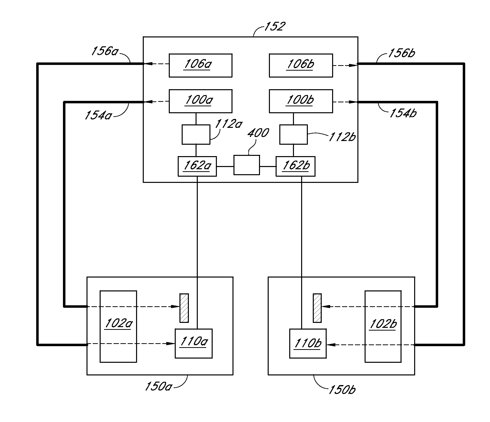
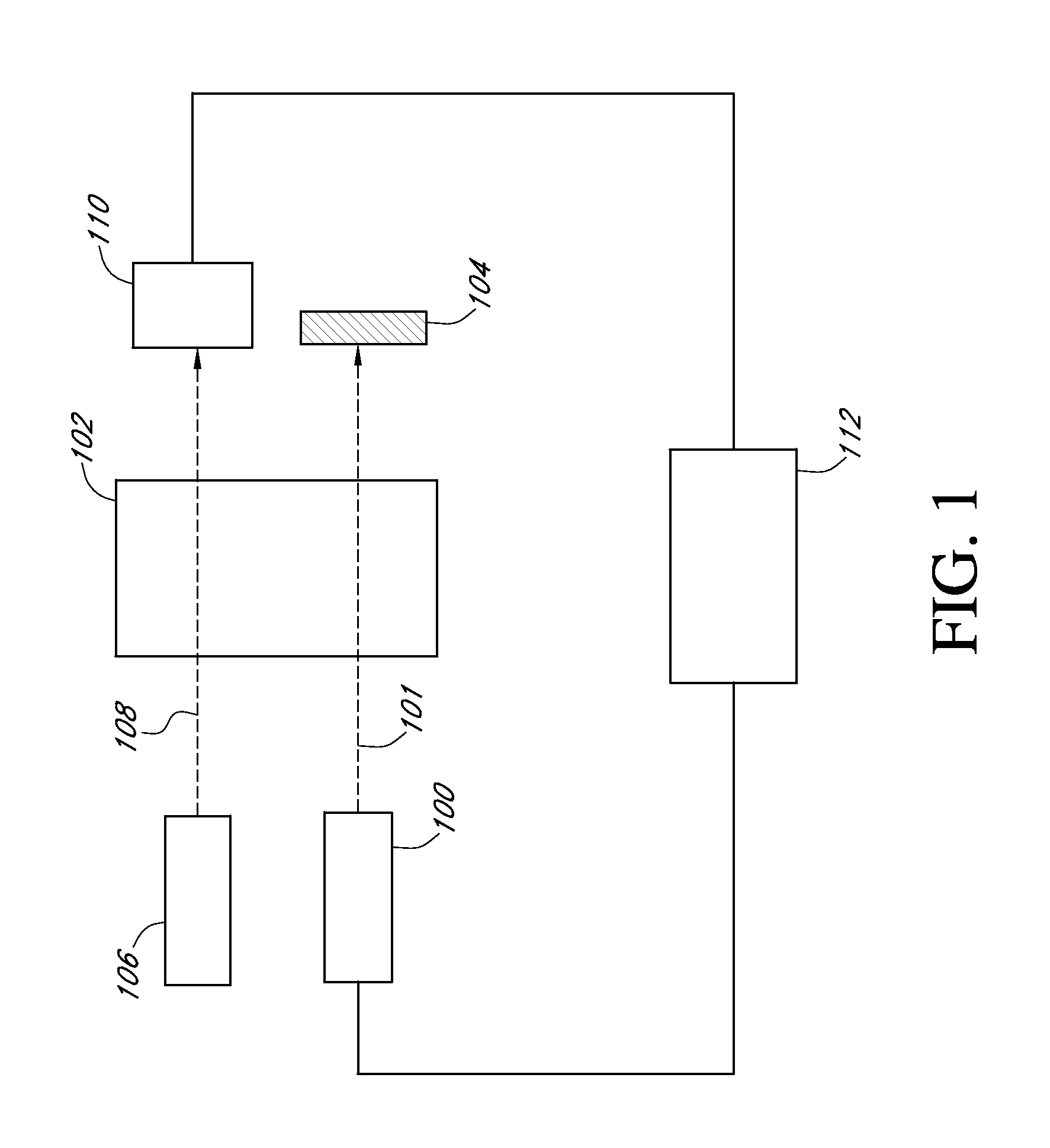
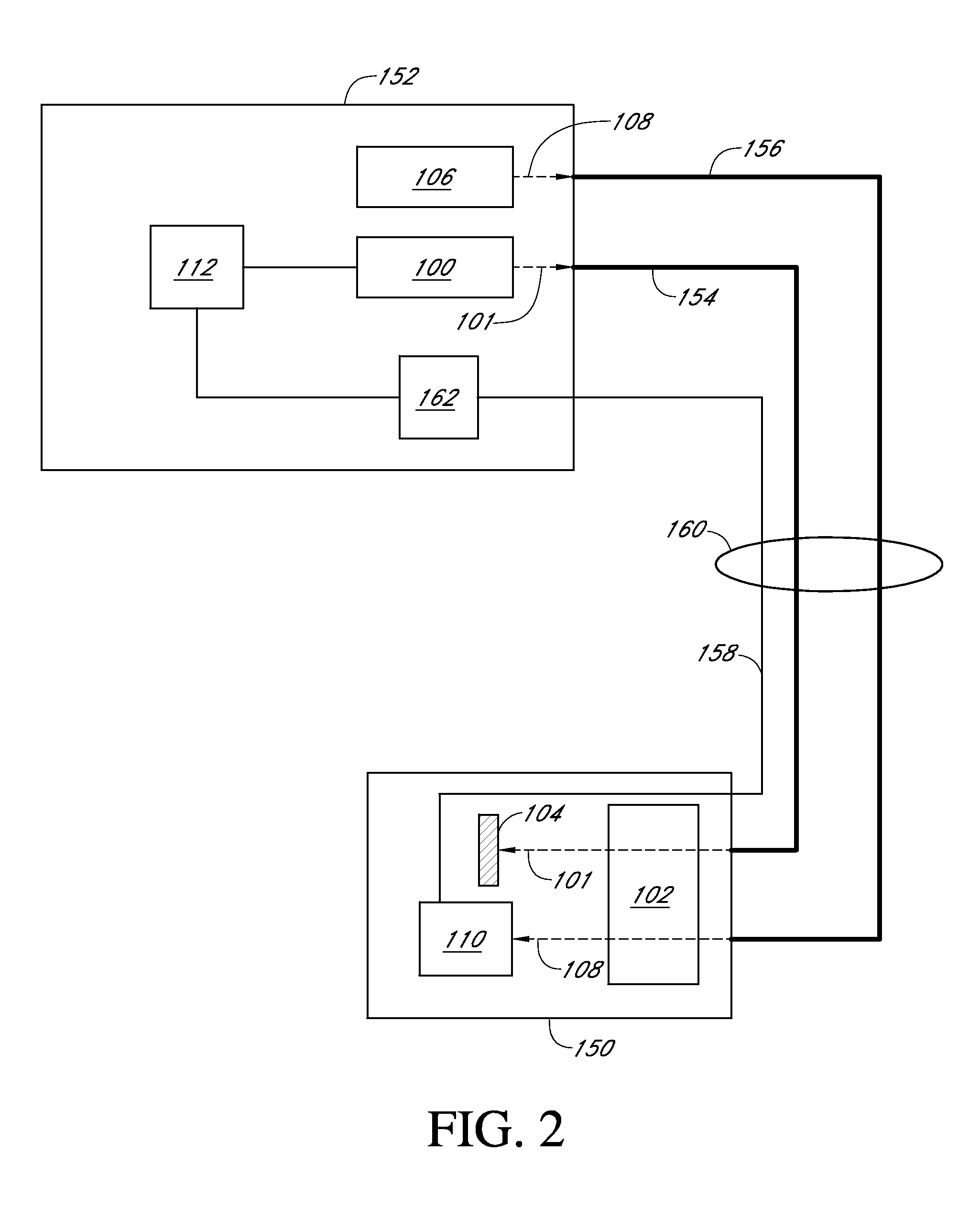
[0023]One embodiment includes a magnetometer that utilizes nonlinear magneto-optical rotation (NMOR) with a modulated pump light source and a non-modulated probe light source. An NMOR resonance occurs when optical pumping causes an atomic vapor to become dichroic (or birefringent), so that subsequent probe light experiences polarization rotation. In one embodiment, both pump and probe light are linearly polarized and therefore primarily produce and detect atomic alignment (Δm=2 coherences). Magnetic-field dependence of the polarization rotation originates from the fact that the atomic spins undergo Larmor precession in the presence of an external magnetic field. Weak optical pumping can only produce a macroscopic alignment when the Larmor precession frequency is small compared to the spin relaxation rate, or alternatively, when optical pumping is modulated nearly synchronous with precession. If the optical-pumping rate is modulated at a frequency ν, then the optical-rotation angle o...


PUM


Abstract

An optical atomic magnetometers is provided operating on the principles of nonlinear magneto-optical rotation. An atomic vapor is optically pumped using linearly polarized modulated light. The vapor is then probed using a non-modulated linearly polarized light beam. The resulting modulation in polarization angle of the probe light is detected and used in a feedback loop to induce self-oscillation at the resonant frequency.

Description

RELATED APPLICATIONS[0001]This application claims the benefit of U.S. Provisional Application No. 60 / 970,242, filed Sep. 5, 2007, which is incorporated herein by reference in its entirety.STATEMENT REGARDING FEDERALLY SPONSORED R&D[0002]The U.S. Government has a paid-up license in this invention and the right in limited circumstances to require the patent owner to license others on reasonable terms as provided for by the terms of Contract No. DE-AC02-05CH11231 awarded by the Department of Energy.BACKGROUND[0003]1. Field of the Invention[0004]The present invention relates to magnetometers.[0005]2. Description of the Related Art[0006]Several applications require the detection of magnetic field strength. Examples of such applications include both pure science endeavors as well as practical applications. Pure science investigations that require the use of sensitive magnetometers include the detection of planetary and solar magnetic fields and the detection of an electric dipole moment i...

Claims


Application Information

Patent Timeline
Patent Type & Authority Patents(United States)
IPC IPC(8): G01R33/26
CPCG01R33/26
Inventor BUDKER, DMITRYHIGBIE, JAMESCORSINI, ERIC P.
Owner RGT UNIV OF CALIFORNIA
Why Eureka
Try Eureka