

Reed switch assembly of magnetic latching relay
a latching relay and relay assembly technology, applied in circuit-breaking switches, dynamo-electric relays, contact mechanisms, etc., can solve problems such as unstable magnetic latching relays, and achieve the effect of enhancing the reliability of magnetic latching relays and high surge curren
- Summary
- Abstract
- Description
- Claims
- Application Information
AI Technical Summary
Benefits of technology
Problems solved by technology
Method used
Image

Examples
Embodiment Construction
[0014]Embodiments of the present invention will now be described, by way of example only, with reference to the accompanying drawings.
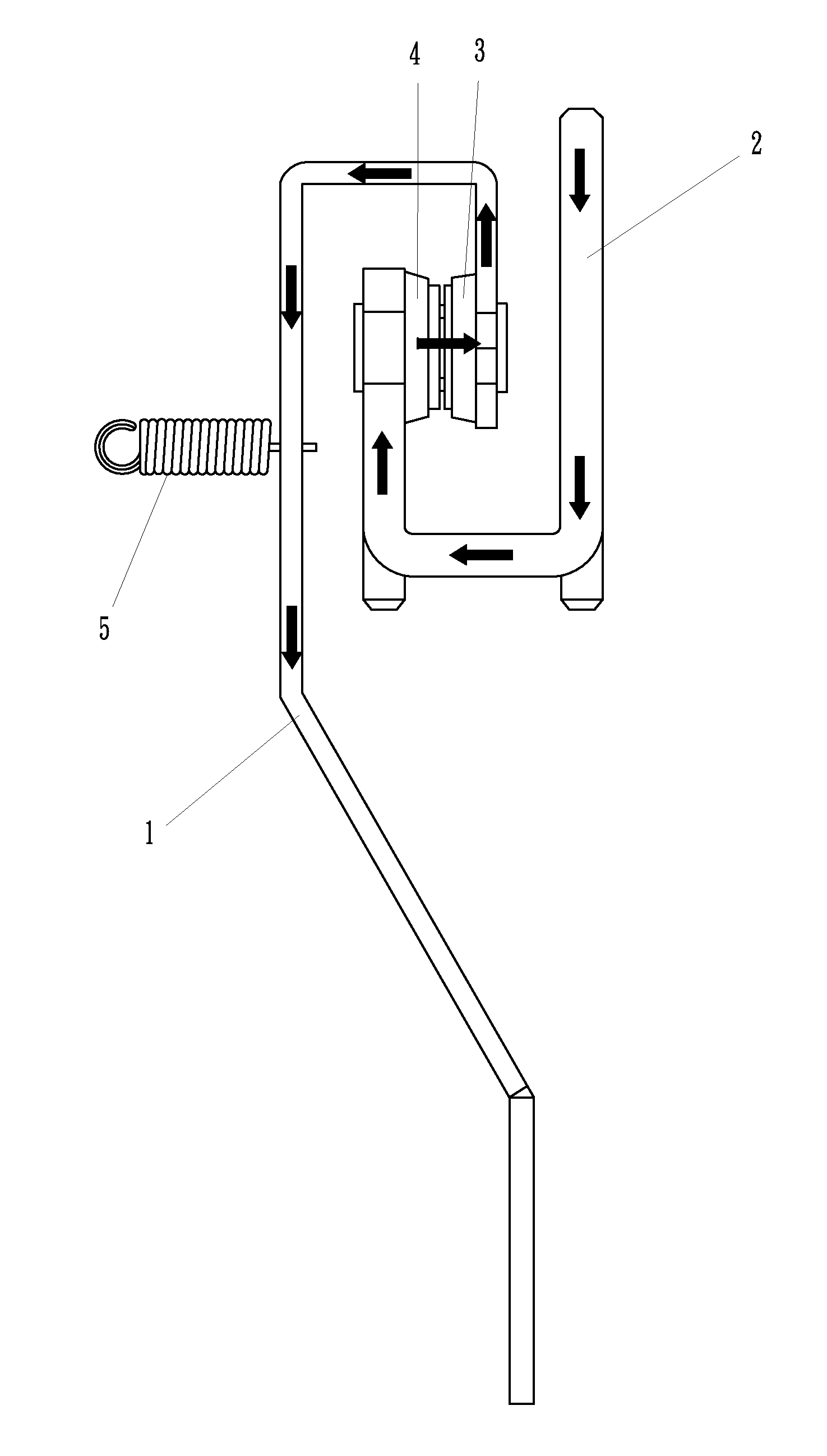
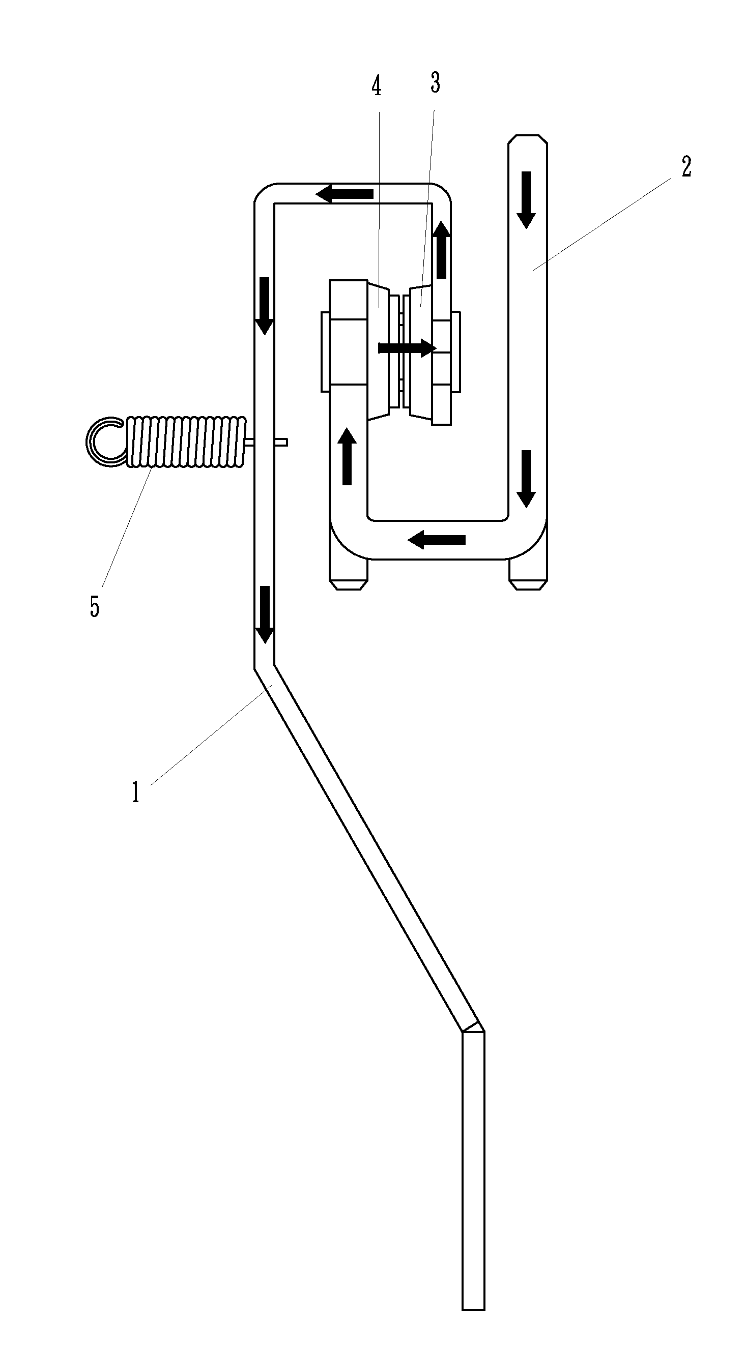
[0015]As shown in FIG. 1, the reed switch assembly of a magnetic latching relay of the present invention comprises a movable reed 1, an immovable reed 2, a movable contact 3, an immovable contact 4 and a tension spring 5. The movable contact 3 and the immovable contact 4 are disposed at respective ends of the movable reed 1 and the immovable reed 2. The end with the movable contact 3 of the movable reed 1 is bent twice at 90 degrees to form a reverse U-shaped end. The end with the immovable contact 4 of the immovable reed 2 is bent twice at 90 degrees to form a U-shaped end. The reverse U-shaped end of the movable reed 1 and the U-shaped end of the immovable reed 2 are interlaced. One end of the tension spring 5 is fixed to the reverse U-shaped end of the movable reed 1, and another end of the tension spring 5 is mounted to a base of the magnetic latc...
PUM
 Abstract
Description
Claims
Application Information