
Liquid crystal panel driving device, method for driving liquid crystal panel, liquid crystal display device, and in-vehicle display device

a technology of liquid crystal display and driving device, which is applied in the direction of electric digital data processing, instruments, computing, etc., can solve the problems of deteriorating display quality, inability to achieve improvement in display quality, and falling waveforms, so as to improve display quality and reduce the effect of falling waveforms

Active Publication Date: 2013-11-19
SHARP KK
View PDF29 Cites 1 Cited by
  • Summary
  • Abstract
  • Description
  • Claims
  • Application Information

AI Technical Summary

Benefits of technology

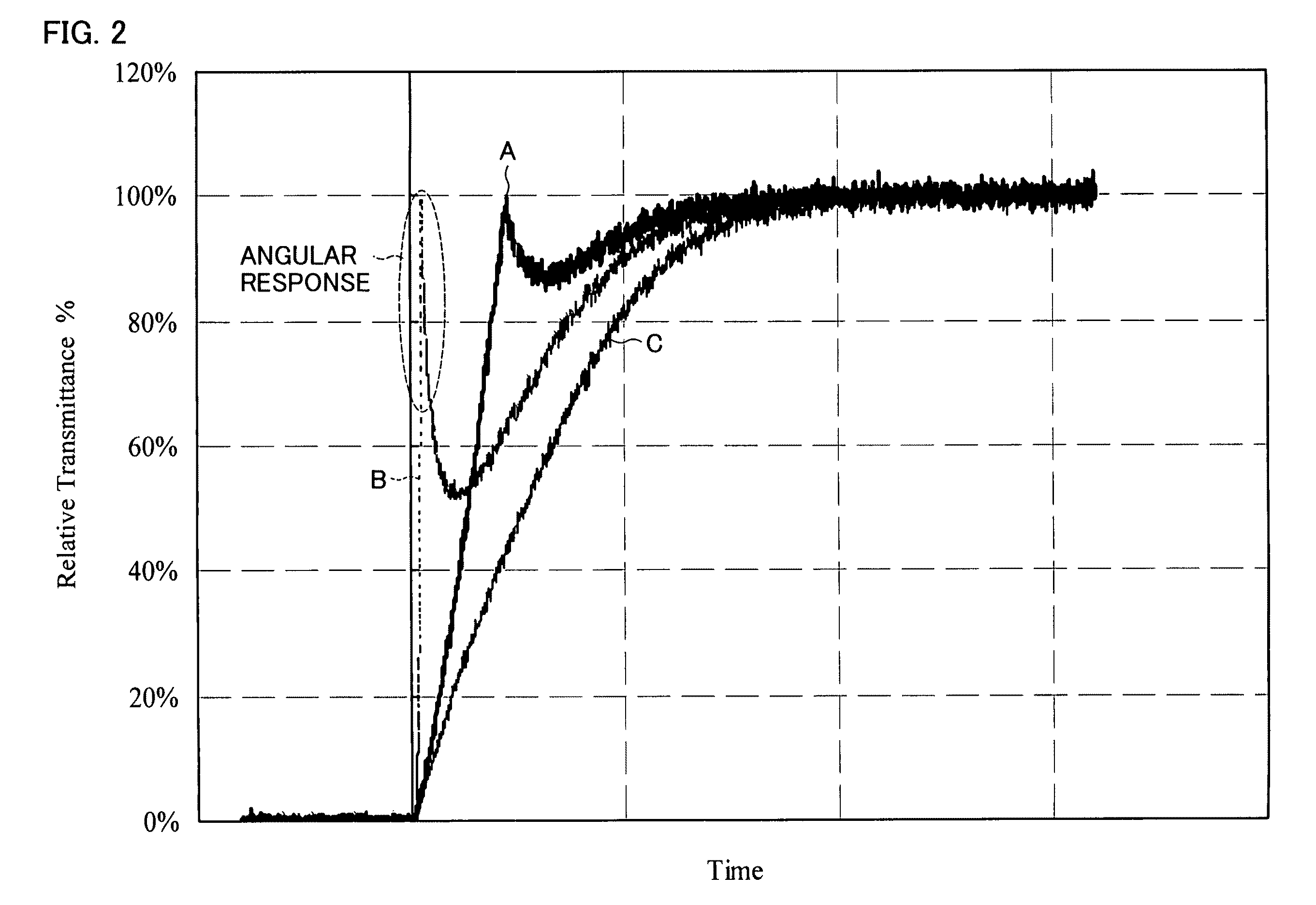
The present invention aims to improve the display quality, particularly the moving image display quality, of a liquid crystal panel driving device at low temperatures. More specifically, the invention uses overdrive to intentionally lower the output gray scale of a rise type gray scale transition when no response condition exists. This allows for a uniform gray scale in each region within the pixel, which reduces the falling of the waveform and prevents angular response, resulting in improved display quality.

Problems solved by technology

Such an in-vehicle liquid crystal display device is demanded that a moving image display performance be secured even at a low temperature (an ultracold temperature) in a range of approximately −30° C. to −20° C. However, a liquid crystal responds slowly at such an ultracold temperature, thereby causing a problem that a moving image display quality, in particular, is deteriorated.
Thus, a liquid crystal display device (e.g., an in-vehicle liquid crystal display device), in which it is required to carry out a moving image display even at a low temperature, causes the following problem.
That is, even if the gray scale transition emphasis process is carried out so as to quicken a response time of the liquid crystal at the low temperature, improvement in the display quality cannot be obtained due to the generation of the angular response.

Method used


Image

  • Liquid crystal panel driving device, method for driving liquid crystal panel, liquid crystal display device, and in-vehicle display device
  • Liquid crystal panel driving device, method for driving liquid crystal panel, liquid crystal display device, and in-vehicle display device
  • Liquid crystal panel driving device, method for driving liquid crystal panel, liquid crystal display device, and in-vehicle display device

Examples


Embodiment Construction

[0056]One embodiment of the present invention is described below with reference to FIGS. 1 through 11.

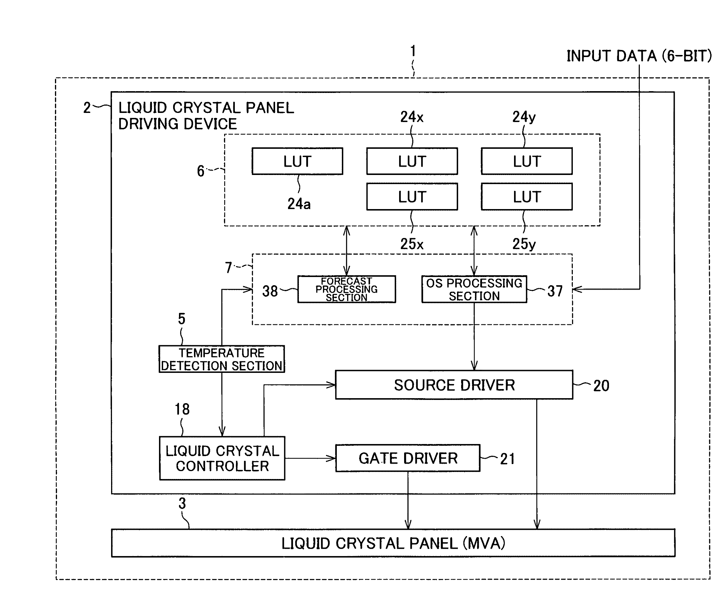
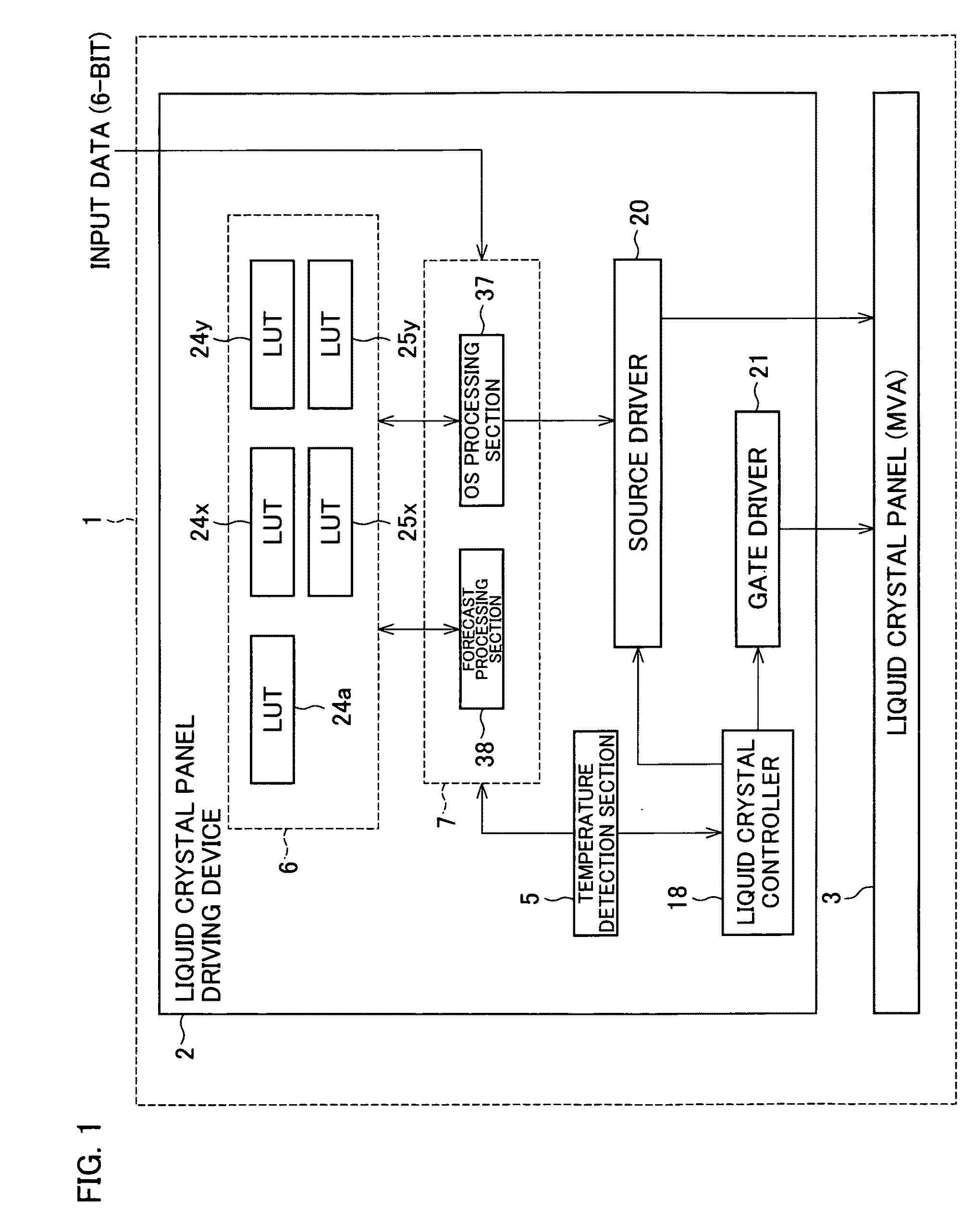
[0057]As shown in FIG. 1, a liquid crystal display device 1 of the present embodiment includes an in-vehicle liquid crystal panel 3 (e.g., a liquid crystal panel for use in an instrumental panel) and a liquid crystal panel driving device 2 for driving the liquid crystal panel 3.

[0058]The liquid crystal panel driving device 2 includes a temperature detection section 5, a storage section 6, a signal processing section 7, a liquid crystal controller 18, a source driver 20, and a gate driver 21. The signal processing section 7 includes an OS (overshoot) processing section 37 and a forecast processing section 38. The storage section 6 includes various types of look up tables (LUTs). The liquid crystal controller 18 and the parts constituting the signal processing section 7 can be realized by a processor such as ASIC.

[0059]The liquid crystal panel 3 adopts a multi-domain vertical alignmen...


PUM


Abstract

In one embodiment of the present application, a liquid crystal panel drive device includes a signal processing section for determining an output gray scale in accordance with a gray scale transition from the gray scale which is forecasted to reach by a previous response to an input gray scale and can carry out overdrive with the output gray scale. At a temperature at which a rise gray scale transition may occur in absence of a response condition does not exist for single overdrive, the signal processing section determines, as an output gray scale, a gray scale lower than a maximum gray scale with respect to a particular gray scale transition out of a rise type gray scale transition. In such a way, a display quality (especially a moving image display quality) at a low temperature can be improved.

Description

TECHNICAL FIELD[0001]The present invention relates to a display device (e.g., an in-vehicle liquid crystal display device) in which a display quality is required at a low temperature.BACKGROUND ART[0002]A liquid crystal display device for use in an in-vehicle display device has recently attracted an attention. Such an in-vehicle liquid crystal display device is demanded that a moving image display performance be secured even at a low temperature (an ultracold temperature) in a range of approximately −30° C. to −20° C. However, a liquid crystal responds slowly at such an ultracold temperature, thereby causing a problem that a moving image display quality, in particular, is deteriorated.[0003]Overdrive (a gray scale transition emphasis process) is known as a technique for quickening a response time of the liquid crystal. According to the overdrive, (i) a gray scale of higher than a current input gray scale is outputted in a case where the current input gray scale is higher than a prev...

Claims


Application Information

Patent Timeline
Patent Type & Authority Patents(United States)
IPC IPC(8): G09G5/10G09G3/36
CPCG02F1/133G09G3/3611G02F1/133707G02F2001/133397G02F2203/30G09G2320/0233G09G2320/0252G09G2320/0261G09G2320/0285G09G2320/041G09G2340/16G02F1/133397
Inventor HONGO, KOKIFURUKAWA, TOMOOFUJIOKA, KAZUYOSHI
Owner SHARP KK
Learn More