Optical transceiver assembly with transmission-direction control

Active Publication Date: 2013-11-19
ASTRIUM SAS
View PDF32 Cites 7 Cited by
  • Summary
  • Abstract
  • Description
  • Claims
  • Application Information

AI Technical Summary

Benefits of technology

The present invention provides a system that can allow for the measurement of angular deviation during the tracking step without affecting the detection of signals. Additionally, the system allows for the continuous transmission of data during the tracking step without reducing the time available for data transmission. The direction of transmission can be accurately determined by computing the centroid of the points where the signals are detected. The system can also include an assembly of multiple reflectors or an attenuation device to adjust power and prevent saturation of the photodetectors. These improvements enhance the accuracy and efficiency of the tracking system.

Problems solved by technology

Such a measurement of the angular deviation cannot be performed during a tracking step, because the reflector at least partially obscures the optical entrance field of the terminal.
A pointing error then results from the use of one and same co-alignment angle value for a prolonged duration.
Errors result from this in the decoding of the received data.

Method used


Image

  • Optical transceiver assembly with transmission-direction control
  • Optical transceiver assembly with transmission-direction control
  • Optical transceiver assembly with transmission-direction control

Examples


Embodiment Construction

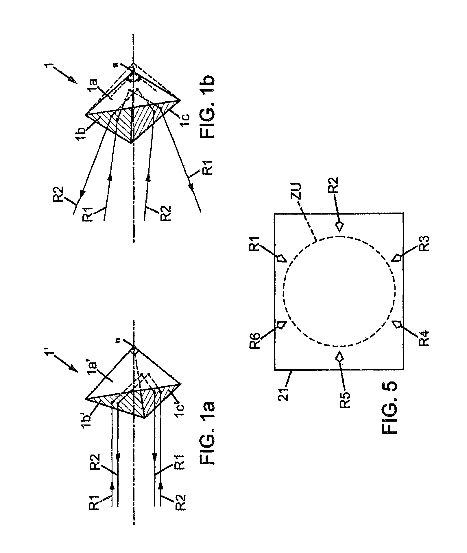
[0036]To make it easier to understand a retroreflector that may be used in the present invention, a known retroreflector of the prior art is first described with reference to FIG. 1a. This retroreflector, which is given the overall reference 1′, consists of three planar mirrors 1a′, 1b′ and 1c′. Each mirror has the shape of a right-angled isosceles triangle. The mirrors are placed so as to form a corner cube: they have edges that are contiguous with each other, and the three mirrors have their respective right angles that are joined together to form the apex of the cube marked Σ. In this situation, a ray R1 or R2 which enters through the aperture of the retroreflector 1′ is reflected successively by the three mirrors 1a′, 1b′ and 1c′ and comes out parallel to itself. The direction of emergence of each ray is independent of the order of the respective reflections of the ray on the mirrors 1a′, 1b′ and 1c′. In practice, the two angles of each of the mirrors 1a′, 1b′ and 1c′ that are n...


PUM


Abstract

An optical transceiver assembly comprises a transmission system, a reception system and a coupling system which directs a part of the signals produced by the transmission system to the reception system. Said part of the transmission signals is detected by a photodetector matrix of the reception system, outside an useful zone of the matrix which is dedicated to the detection of the received signals. A transmission direction may therefore be determined in real time while the received signals are detected. A difference between the transmission direction and a reception direction of the transceiver assembly may then be precisely compensated for at each moment during a tracking step. The transceiver assembly may be a free space laser optical communication terminal.

Description

CROSS-REFERENCE TO RELATED APPLICATIONS[0001]This application claims priority under the Paris Convention to French Patent Application No. 08 56748, filed on Oct. 6, 2008.FIELD OF THE DISCLOSURE[0002]The present invention relates to a transceiver assembly which is capable of measuring and compensating for, in a continuous and autonomous manner, the angular difference between the direction of transmission and that of reception.BACKGROUND OF THE DISCLOSURE[0003]It applies in particular to a free space laser optical communication terminal.[0004]Free space laser optical communication is used for transmitting data between two points which may move relative to one another. For example, it may be used for a communication between two artificial satellites, between a satellite and an aircraft, a satellite and a ground terminal, etc.[0005]In this transmission method, two terminals that are in mutual communication each produce a laser beam towards the other terminal. Each terminal is simultaneo...

Claims


Application Information

Patent Timeline
IPC IPC(8): H04B10/00H04B10/118
CPCH04B10/118
Inventor VAILLON, LUDOVICPLANCHE, GILLES
Owner ASTRIUM SAS
Why Eureka
Try Eureka