
Magnetic flow meters with automatic field maintenance

a technology of automatic field maintenance and flow meters, which is applied in the direction of liquid/fluent solid measurement, instruments, ac/dc measuring bridges, etc., can solve the problems of serious economic consequences, failures may go undetected for a long time, and undetected field failures of magnetic flow meters, etc., to achieve the effect of minimizing the differen

Inactive Publication Date: 2013-11-26
ONICON INC
View PDF20 Cites 17 Cited by
  • Summary
  • Abstract
  • Description
  • Claims
  • Application Information

AI Technical Summary

Benefits of technology

The present invention provides means for monitoring and automatically compensating for changes in a magnetic flow meter during its operation. This is achieved through the use of a single voltage source and sampling circuitry to determine the error difference between two output values, with the selected amplification factor being changed accordingly. The invention also provides a method for automatically calibrating the flow meter during routine operation and a method for setting the zero point of the flow meter during operation. The invention addresses small but significant changes that are expected during the service life of the flowmeter and provides alarms indicating the need for service or repair.

Problems solved by technology

Magnetic flow meters are subject to undetected field failures and to various drift errors which can have serious economic consequences.
Diagnostic tests can be performed on magnetic flow meters in the field to determine their operating condition but this typically requires that during the tests, the meters not be measuring flow rate.
This meter down time can discourage operators from making the tests so that failures may go undetected for a long time.

Method used


Image

  • Magnetic flow meters with automatic field maintenance
  • Magnetic flow meters with automatic field maintenance
  • Magnetic flow meters with automatic field maintenance

Examples


Embodiment Construction

[0016]In studying this Detailed Description, the reader may be aided by noting definitions of certain words and phrases used throughout this patent document. Wherever those definitions are provided, those of ordinary skill in the art should understand that in many, if not most, instances such definitions apply both to preceding and following uses of such defined words and phrases.

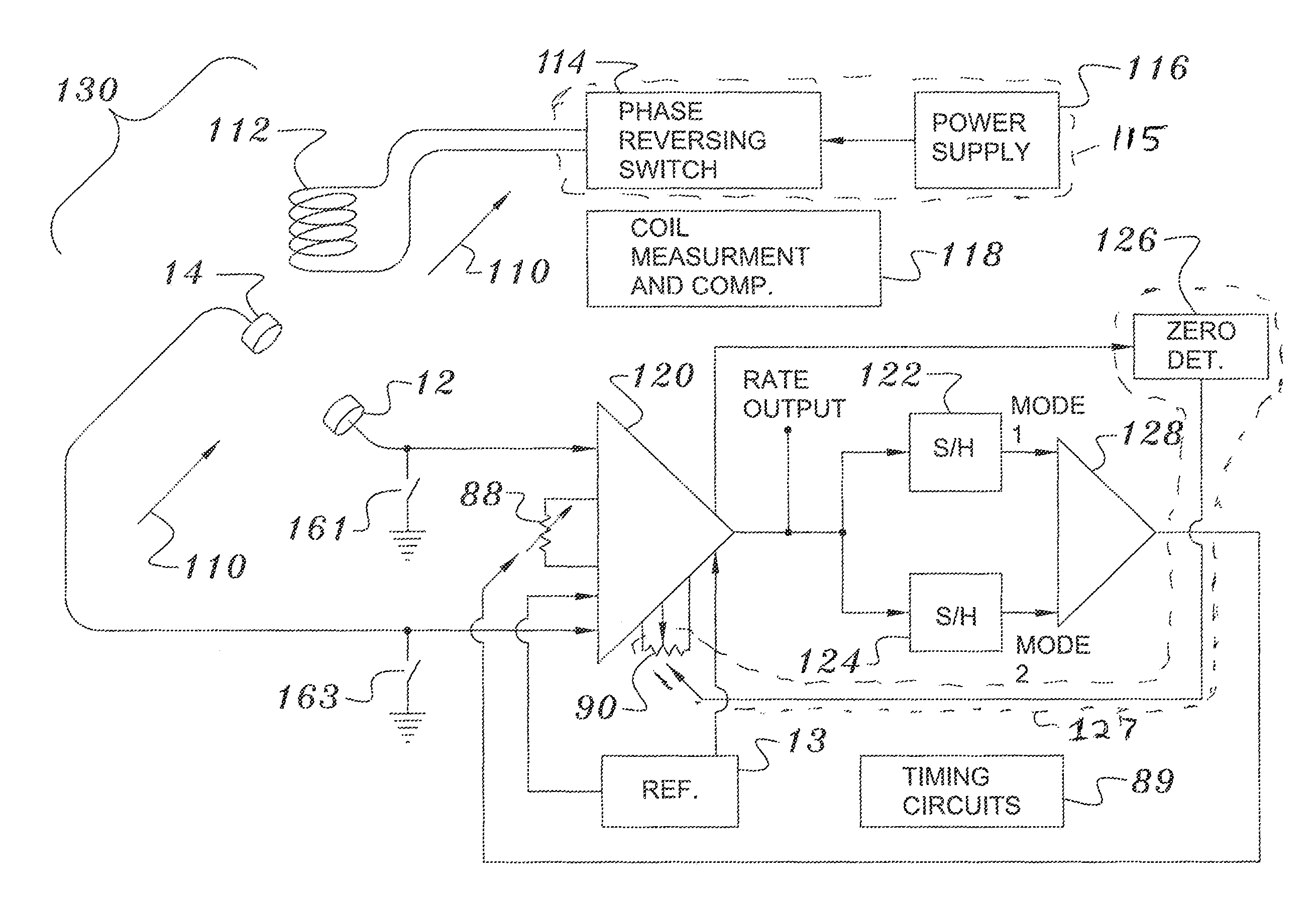
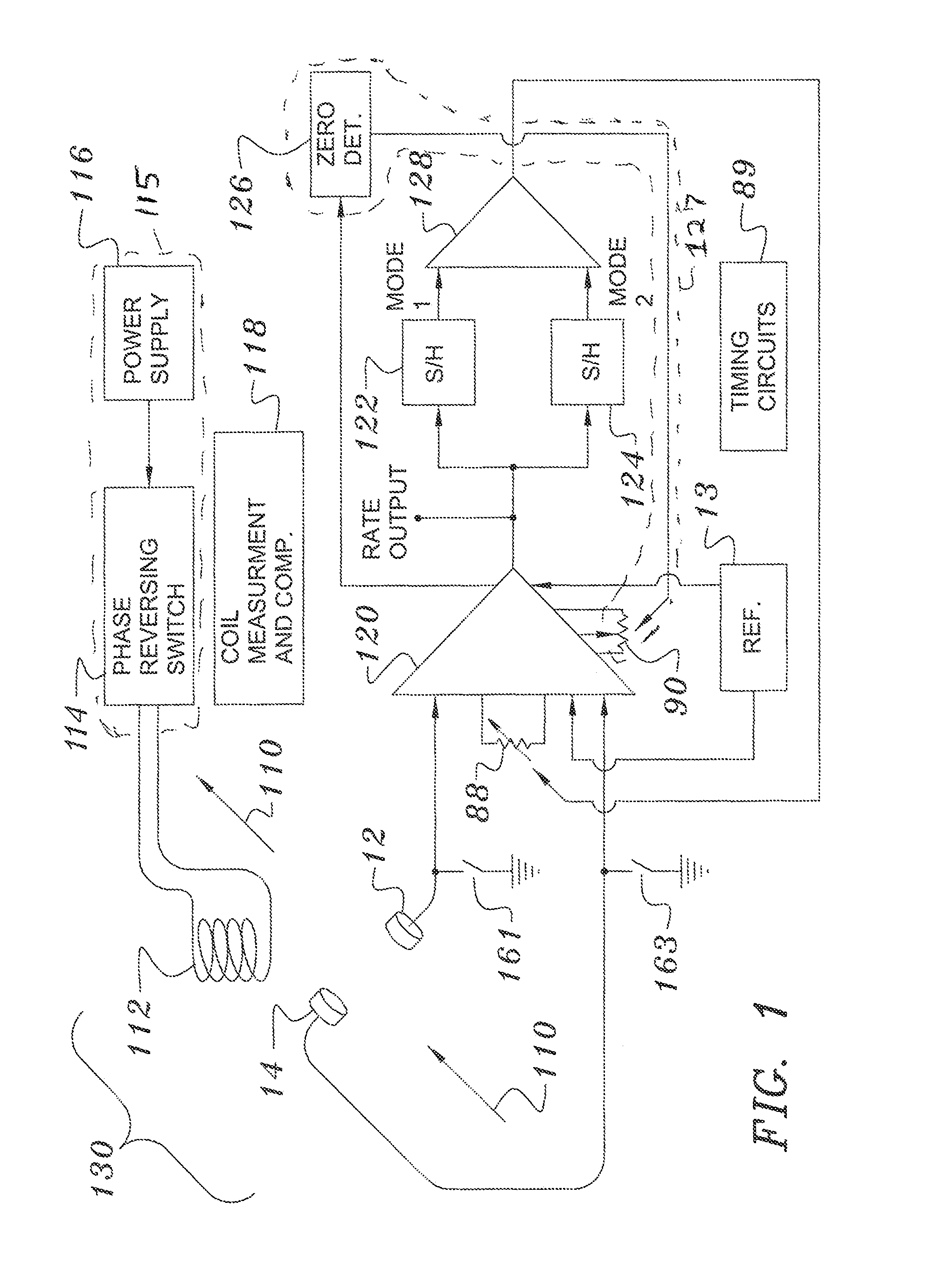
[0017]Four major areas are addressed for diagnostic monitoring and automatic compensation and one or more of them may be used as desired. They are signal amplification or span, meter zero, electrode maintenance and magnetic flux determination. In FIG. 1, a simplified block diagram of a magnetic flow meter 130 is shown. Here the electrodes 12 and 14 detect the signals generated in the flowing fluid 110 in which an electromagnet 112 produces a magnetic flux orthogonal to both the axis between the electrodes and the axis of the flowing fluid. The coil inductance and resistance are measured by a circuit 118 to ...


PUM


Abstract

Zero and calibration drift errors in a magnetic flow meter can be detected and automatically corrected. A zero error can be detected by measuring an amplifier output when the meter's electromagnet is inactive. Automatic calibration of the span can be done by adding a signal to a measured electrode voltage at an amplifier input, subtracting the expected amplified value of that signal at the output and adjusting the amplifier gain responsive to the difference in signal magnitude.

Description

BACKGROUND OF THE INVENTION[0001]The invention relates to measuring the rate of flow of conducting fluids by electromagnetic induction (i.e., Faraday meters). More specifically, the invention relates to in situ calibration of such instruments.BACKGROUND INFORMATION[0002]Magnetic flow meters provide output flow rate signals having a magnitude proportional to an amplification scaling factor of an amplifier circuit used to boost the electromagnetically generated signals to the desired output levels.[0003]Magnetic flow meters are subject to undetected field failures and to various drift errors which can have serious economic consequences. Diagnostic tests can be performed on magnetic flow meters in the field to determine their operating condition but this typically requires that during the tests, the meters not be measuring flow rate. This meter down time can discourage operators from making the tests so that failures may go undetected for a long time.[0004]There is thus a need to provi...

Claims


Application Information

Patent Timeline
Patent Type & Authority Patents(United States)
IPC IPC(8): G01F1/60
CPCG01F1/60G01F25/0007G01F25/10
Inventor FELLER, MURRAY F
Owner ONICON INC
Learn More