
Ignition coil

a technology of ignition coil and coil body, which is applied in the direction of ignition safety means, machines/engines, instruments, etc., can solve the problems of not being able to gnaw the ignition cable by rodents, not being able to achieve the effect of avoiding diagnostic errors

Inactive Publication Date: 2013-11-26
ROBERT BOSCH GMBH
View PDF30 Cites 0 Cited by
  • Summary
  • Abstract
  • Description
  • Claims
  • Application Information

AI Technical Summary

Benefits of technology

[0011]Because of the design according to the exemplary embodiments and / or exemplary methods of the present invention of an ignition coil, the principle of capacitive coupling of the secondary winding for diagnostic purposes may be maintained. However, according to the exemplary embodiments and / or exemplary methods of the present invention, a component of the ignition coil itself is used as the capacitive coupling element, which is electrically connected to a terminal of the ignition coil. Consequently, one may couple out a diagnostic signal that is able to be evaluated. On the one hand, this has the advantage that this function is fulfilled without an additional external component, and on the other hand, the diagnostic signal is able to be processed online by an additional fixed internal connection in the ignition coil and the cable connection to the control unit by suitable means, e.g. an electronic circuit or software, that is, during the running operation in the engine / vehicle, for instance, to satisfy the OBD regulations.
[0012]Thus, it turns out in particular that the recording of measurements and the diagnostic signal is able to take place, and that the diagnostic signal may be coupled out in a simple manner, a manual intervention, e.g. applying or coupling the measuring probe not being necessary. Furthermore, the specified distance of the component from the high-voltage winding and its specified flatness yield a reproducible signal over all ignition coils of one kind, and thus an inadequate signal quality in conjunction with an insufficient coupling that is manual, as a rule, no longer exists, whereby diagnostic errors are able to be avoided. Moreover, permanent online processing or 100% evaluation of the signal is possible, and the signal may be processed further at will, for instance, for engine control, a shop diagnosis, measuring systems for functional analysis, development and the release of ignition systems, etc.

Problems solved by technology

In addition, functional safety is increased by the reduction in components, for instance, the gnawing of the ignition cable by rodents is no longer possible.
However, because of the rotational symmetry, they are clearly different in design from compact ignition coils.
But, because of the direct insertion of current ignition coils into the cylinder head, an electrical diagnosis of the functioning can be carried out only with difficulty or not at all.
In the newer ignition coil designs this is partially no longer possible since, based on tightened space, the ignition coil is not accessible, or the coupling to the high-voltage winding using a measuring probe is not possible, for instance, based on a missing outer air gap of the ignition coil, or only by a design approach that requires great additional constructional effort.

Method used


Image

  • Ignition coil
  • Ignition coil
  • Ignition coil

Examples


Embodiment Construction

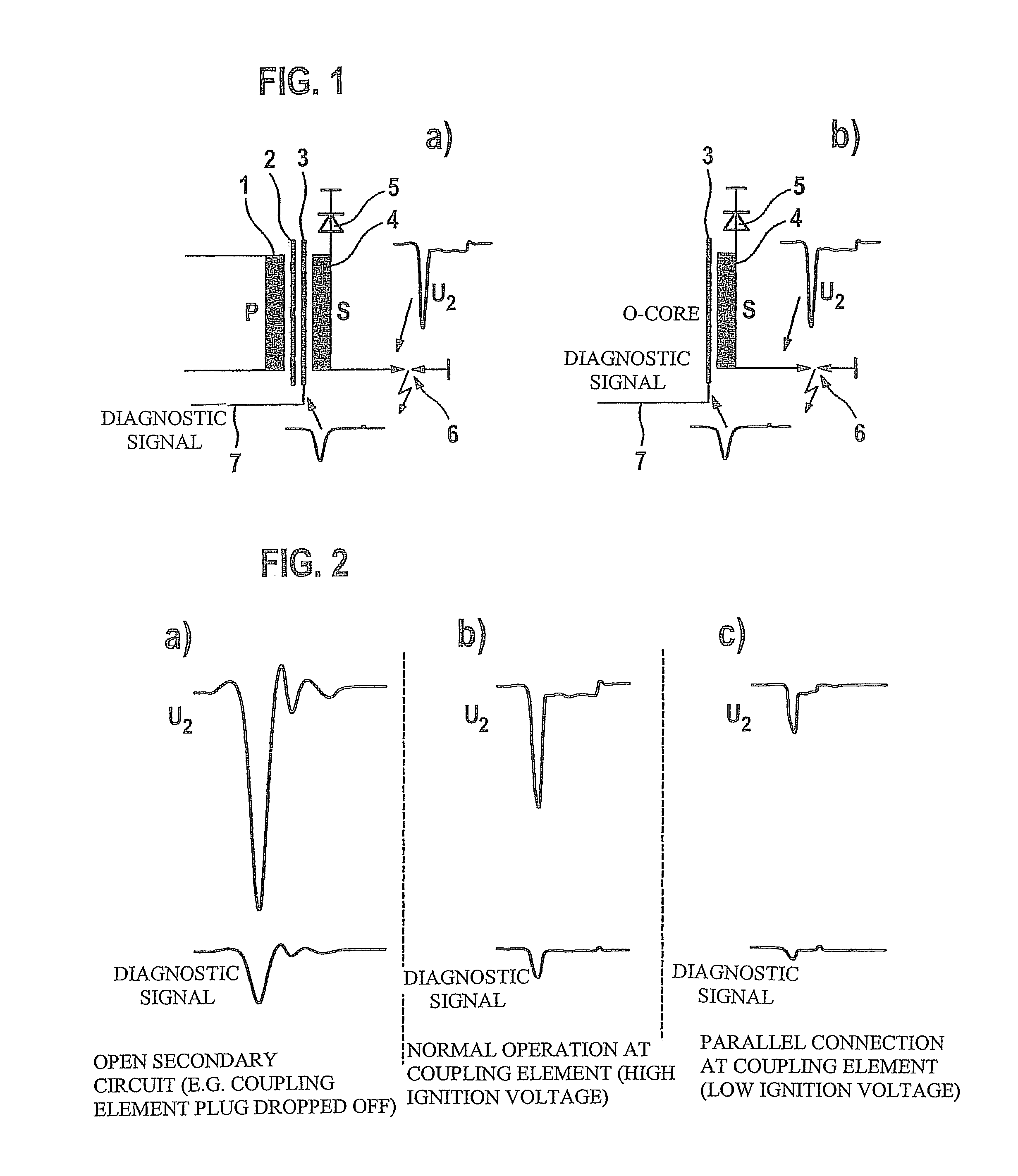
[0026]FIG. 1 shows a schematic representation of an ignition coil according to a first exemplary embodiment of the present invention. A primary, or low-voltage winding 1, that is connected via an ignition output stage, that is not shown, to a battery that is also not shown, is coupled via a magnetic core, which is composed in this case of an I core 2 and an O core 3, to a secondary, or high-voltage winding 4, whose one end is connected to ground via an EFU diode 5, and whose other end is connected to ground via a spark plug 6. A signal line 7 is connected at O core 3, for picking off a diagnostic signal. Thus, except for the coupling out of the diagnostic signal via signal line 7, that is, except for signal line 7, what is involved here is the construction of a usual ignition coil. FIG. 1b) shows the coupling out of the diagnostic signal and the relevant components for it of the ignition coil, once more by themselves.

[0027]During the generation of the high-voltage pulse in the ignit...


PUM

PropertyMeasurementUnit
conductiveaaaaaaaaaa
distanceaaaaaaaaaa
voltageaaaaaaaaaa

Abstract

An ignition coil for an Otto engine for an high-voltage winding has a conductive, laminar component, which is at a specified distance from the high-voltage winding and which is electrically connected to a terminal of the ignition coil. In a method for the capacitive coupling of the high-voltage winding of an ignition coil for diagnostic purposes, a conductive, laminar component of the ignition coil, which is at a specified distance from the high-voltage winding and which is electrically connected to a terminal of the ignition coil, is used as a capacitive coupling element.

Description

FIELD OF THE INVENTION[0001]The present invention relates to an ignition coil for an Otto engine, which has a high-voltage winding. Furthermore, the present invention relates to a method for capacitive coupling the high-voltage winding of an ignition coil for diagnostic purposes.BACKGROUND INFORMATION[0002]The ignition coil is that component of the inductive ignition system which generates the high voltage, required for the spark arc-over at the spark plug, from the low battery voltage. It is fed by the DC vehicle electrical system and supplies ignition pulses for the spark plug having the required high voltage and spark energy. This component has continued to be developed further in the course of time and has been adapted to the increased requirements on the Otto engine.[0003]The types of ignition coil used for new developments are essentially compact ignition coils and rod-type ignition coils. In a compact ignition coil, the magnetic circuit is made up of an O core and an I core o...

Claims


Application Information

Patent Timeline
Patent Type & Authority Patents(United States)
IPC IPC(8): H01F38/12
CPCH01F38/12H01F27/40H01F2038/122
Inventor LERCHENMUELLER, KLAUS
Owner ROBERT BOSCH GMBH
Learn More