Image forming apparatus with timer part

a technology of timer and image forming apparatus, which is applied in the direction of electrographic process apparatus, thin material processing, instruments, etc., can solve the problems of reducing the productivity of the image forming apparatus, reducing the conveying capacity, and reducing the risk of paper feeding or paper conveying from roller slippage, so as to ensure productivity

Inactive Publication Date: 2013-11-26
KYOCERA DOCUMENT SOLUTIONS INC
View PDF6 Cites 7 Cited by
  • Summary
  • Abstract
  • Description
  • Claims
  • Application Information

AI Technical Summary

Benefits of technology

[0011]The present disclosure was contrived in view of the problems in the prior art described above, and discloses accurately determining delays or advances in the timing at which paper arrives at the resist part while also taking sheet interval into account, and correcting the paper feeding start timing on the basis of the accurate determination results and causing the paper to always arrive at the resist part at the proper timing so as to ensure productivity.

Problems solved by technology

At this time, the risk of delays in paper feeding or paper conveying from roller slippage, reduced conveying capacity due to roller wear, or the like arises.
Delays in feeding or conveying the paper reduce the productivity of the image forming apparatus.
When the paper in the paper feeding part is fed with the position of its leading end shifted towards the downstream side of the paper conveyance direction, the paper feeding reaches the resist part prematurely.
There is thus the problem that delays or advances in the timing at which the paper arrives at the resist part cannot be correctly determined.
There is the problem that such paper feeding start timing correction may create a sheet interval that is too small.

Method used


Image

  • Image forming apparatus with timer part
  • Image forming apparatus with timer part
  • Image forming apparatus with timer part

Examples


first embodiment

[0025]There follows a description of embodiments of the present disclosure with reference to FIGS. 1 through 11. A first embodiment will first be described with reference to FIGS. 1 through 7. However, the elements of the configurations, arrangements, or the like described in the embodiments are merely for the sake of illustration, and in no way limit the scope of the disclosure.

[0026](Outline of an Image Forming Apparatus)

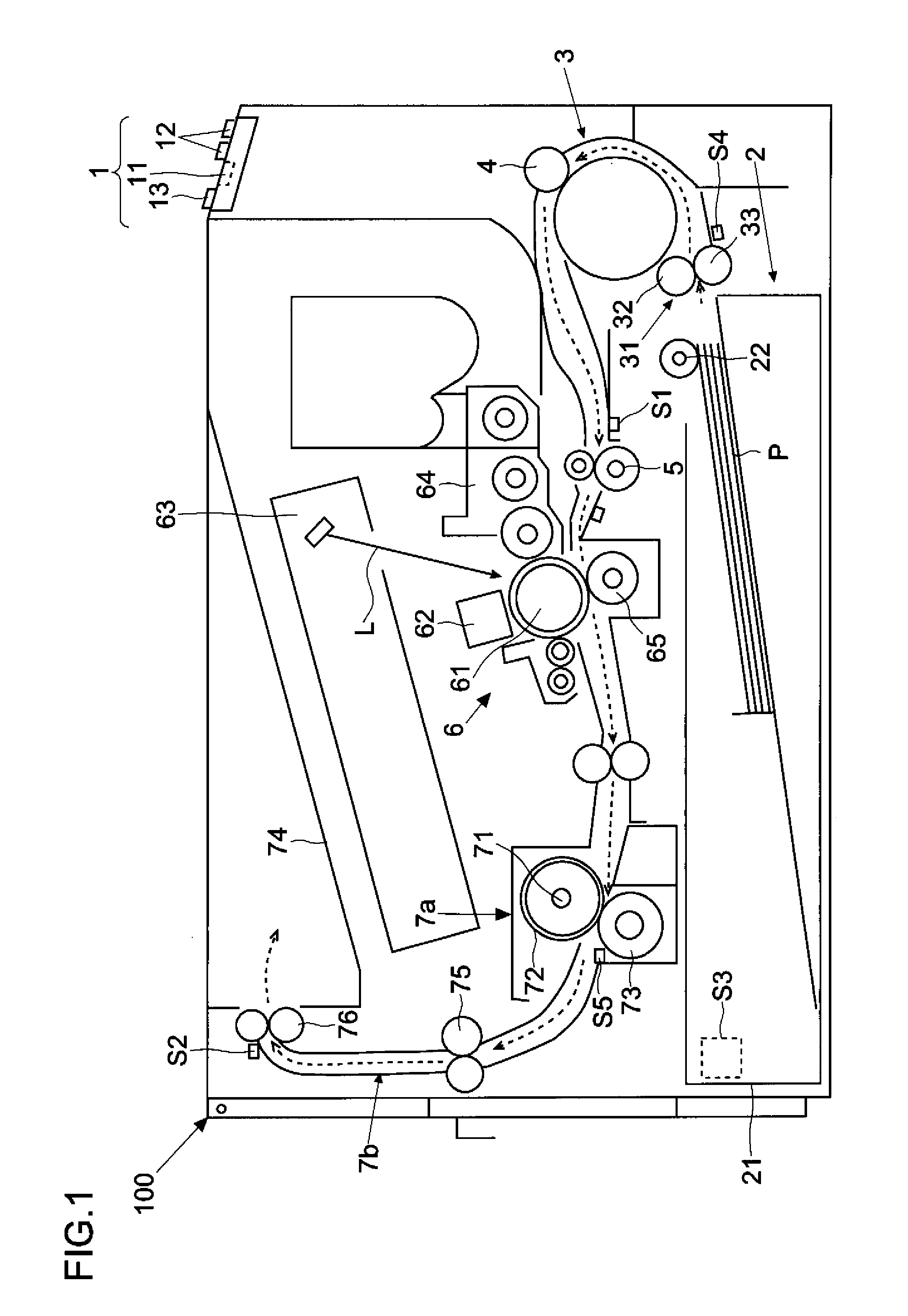
[0027]First, the first embodiment will be described. The following description of the embodiment features an electrophotographic digital printer 100 as an example of an image forming apparatus. FIG. 1 is a schematic left side sectional view of an outline of the structure of the printer 100.

[0028]As shown in FIG. 1, an operating panel 1 (corresponding to an input part) is provided on an upper part of the front side of the printer 100. The operating panel 1 has an LCD 11 (corresponding to an alert-issuing part) for displaying the status of the printer 100 and variou...

second embodiment

[0137](Second Embodiment)

[0138]Next, a process of correcting paper feed start timing in an image forming apparatus (printer 100) according to a second embodiment will be described with reference to FIG. 8. FIG. 8 is a flow chart illustrating an example of a procedure of correcting paper feed start timing in the printer 100 according to the second embodiment.

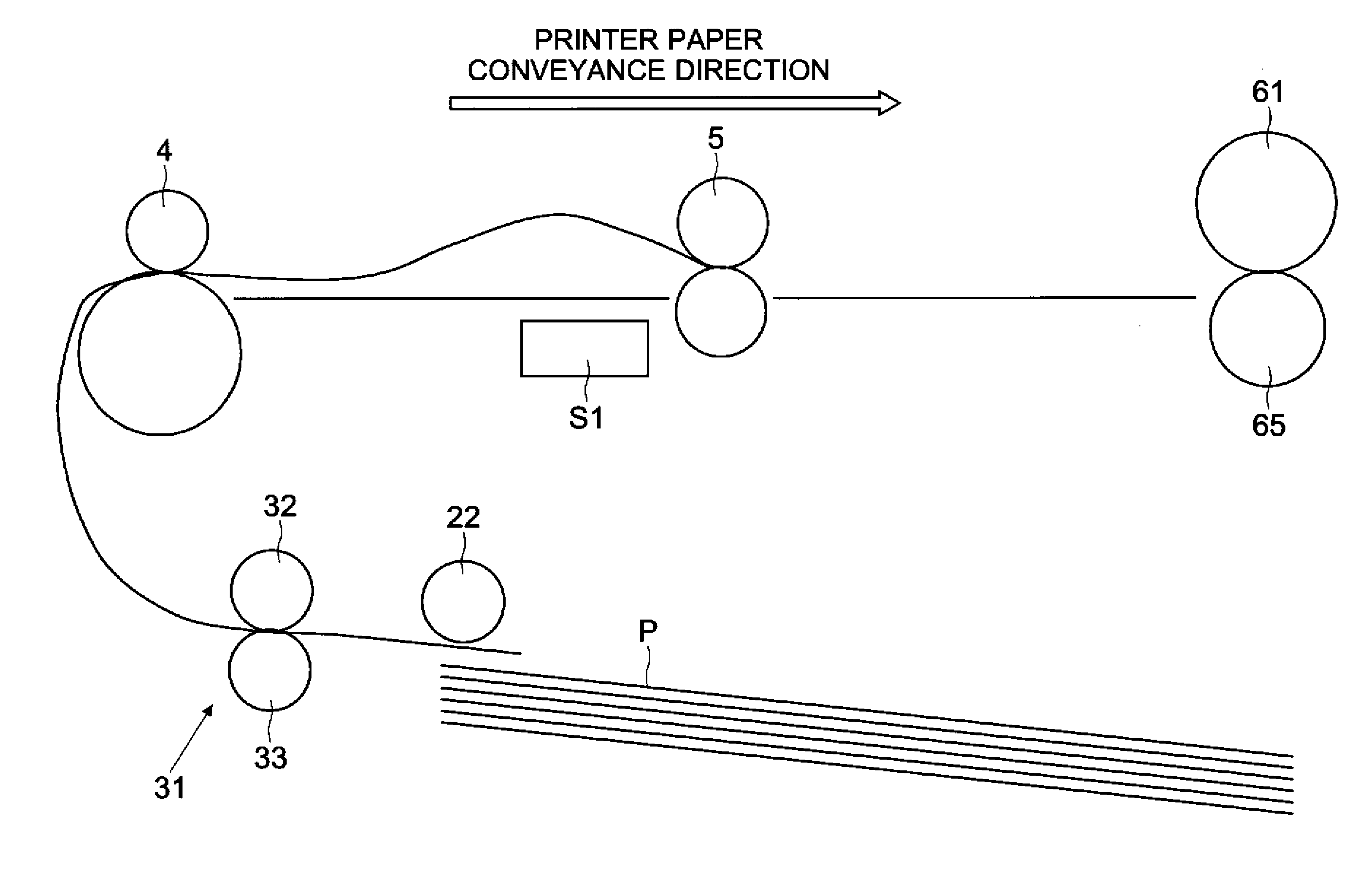
[0139]When actually using the printer 100, spontaneous paper conveyance delays may occur. Correcting the paper feed start timing as described in the first embodiment allows spontaneous paper conveyance delays to be handled. However, delays in paper conveyance (delayed arrival at the resist roller pair 5) also tend to occur as the result of wear or the like in the paper feeding roller 22 or intermediate roller pair 4. In such cases, the paper feed start timing must be corrected in order to order meet the number of sheets printed per unit of time (e.g., ppm) called for in the specifications or design at all times.

[0140]In the first...

third embodiment

[0170](Third Embodiment)

Next, an image forming apparatus (printer 100) according to a third embodiment will be described with reference to FIG. 9. FIG. 9 is a chart illustrating paper feeding and paper conveyance timings in the printer 100 according to the third embodiment.

[0171]The printer 100 according to the present embodiment differs from the first and second embodiments in that the intermediate roller pair 4 is stopped after curl has been formed in the first sheet of paper P, and the intermediate roller pair 4 and resist roller pair 5 are rotated simultaneously. In other words, because time for absorbing delays in paper conveyance is provided before the resist roller pair 5 sends out the paper P in the printer 100 according to the third embodiment, the intermediate roller pair 4 is temporarily stopped for the first sheet of paper P. The intermediate roller pair 4 is not stopped for the second and subsequent sheets. However, the configuration of the printer 100 and the basic phi...


PUM


Abstract

An image forming apparatus comprises an image-forming part; a paper feeding part; a resist part; a rotating body; a detector for detecting the arrival of paper at the resist part; a timer part for measuring a measurement time from when feeding of a second sheet of paper from the paper feeding part is begun to when the detector detects the arrival of the second sheet of paper, and a sheet interval time from when the detector detects the passage of a first sheet of paper immediately preceding the second sheet of paper to when the arrival of the second sheet of paper is detected; and an identifier part for referring to the measurement time, a reference measurement time, the sheet interval time and a reference sheet interval time, and deciding the paper feeding part advancing or delaying the paper feed start timing.

Description

[0001]This application is based upon and claims the benefit of priority from the corresponding Japanese Patent Application No. 2011-165428 filed Jul. 28, 2011, the entire contents of which are incorporated herein by reference.BACKGROUND[0002]1. Field[0003]The present disclosure relates to an image forming apparatus such as a printer, multifunction machine, photocopier, facsimile apparatus, or the like including a resist part for curling and sending out paper.[0004]2. Description of Related Art[0005]An image forming apparatus has a paper feeding part (for example, a paper cassette) for accommodating a plurality of sheets of paper. The image forming apparatus conveys paper supplied from the paper feeding part, and forms an image on the paper. A roller or the like is provided in a conveyance path for conveying the paper. At this time, the risk of delays in paper feeding or paper conveying from roller slippage, reduced conveying capacity due to roller wear, or the like arises. Delays in...

Claims


Application Information

Patent Timeline
Patent Type & Authority Patents(United States)
IPC IPC(8): B65H5/06B65H7/18
CPCG03G15/6564B65H7/18G03G2215/00721
Inventor MARUTA, MASAAKINAKAMURA, SATORU
Owner KYOCERA DOCUMENT SOLUTIONS INC
Why Eureka
Try Eureka