
Apparatus to separate light fluids, heavy fluids, and/or sediment from a fluid stream

a technology of heavy fluids and apparatuses, which is applied in separation processes, sewage draining, and the nature of treatment water, etc., can solve the problems of accumulating rain water, accumulating pollutants, and treating storm water to create additional difficulties

Inactive Publication Date: 2013-11-26
BAYSAVER TECH +1
View PDF9 Cites 0 Cited by
  • Summary
  • Abstract
  • Description
  • Claims
  • Application Information

AI Technical Summary

Benefits of technology

The apparatus effectively treats storm water by diverting and filtering the most contaminated flows, preventing pollutant release and flooding, and maintaining system functionality during intense storms, ensuring efficient pollutant removal and preventing system backups.

Problems solved by technology

This results in an accumulation of the rain water prior to discharge into the watershed.
Because impervious surfaces typically have been paved for a purpose, they will have vehicles, activity and / or traffic on them, which will cause an accumulation of pollutants between rain events.
Consequently, treating storm water creates additional difficulties because the system must be able to clean the water yet be able to pass very intense storms without flow slowdowns or backups that could cause flooding.

Method used


Image

  • Apparatus to separate light fluids, heavy fluids, and/or sediment from a fluid stream
  • Apparatus to separate light fluids, heavy fluids, and/or sediment from a fluid stream
  • Apparatus to separate light fluids, heavy fluids, and/or sediment from a fluid stream

Examples


Embodiment Construction

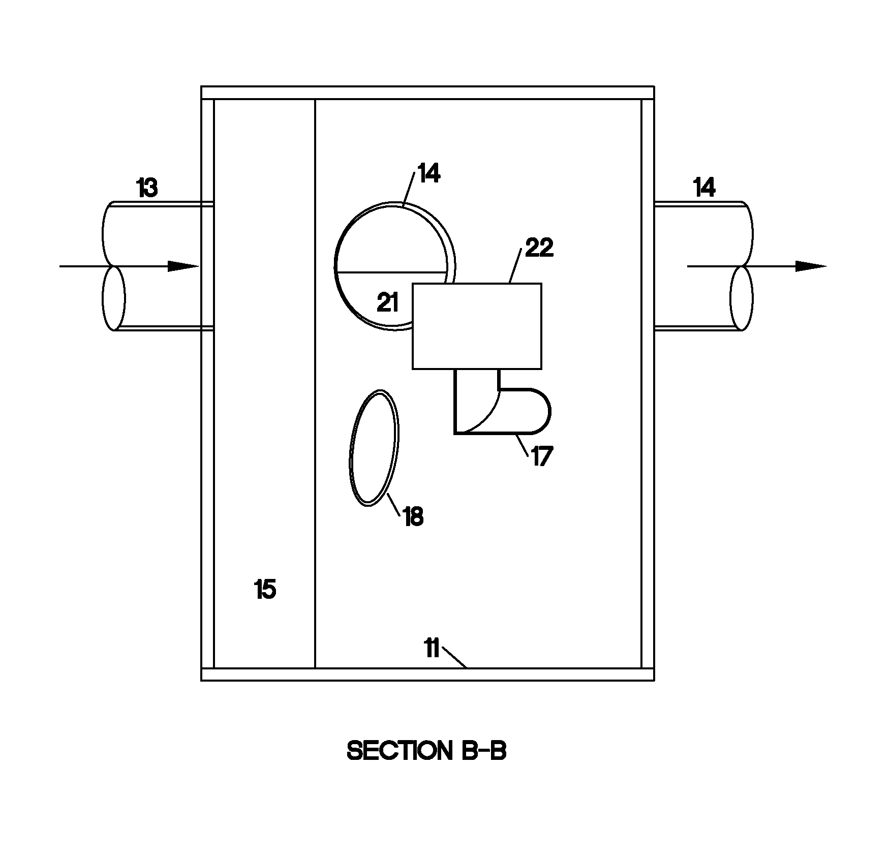
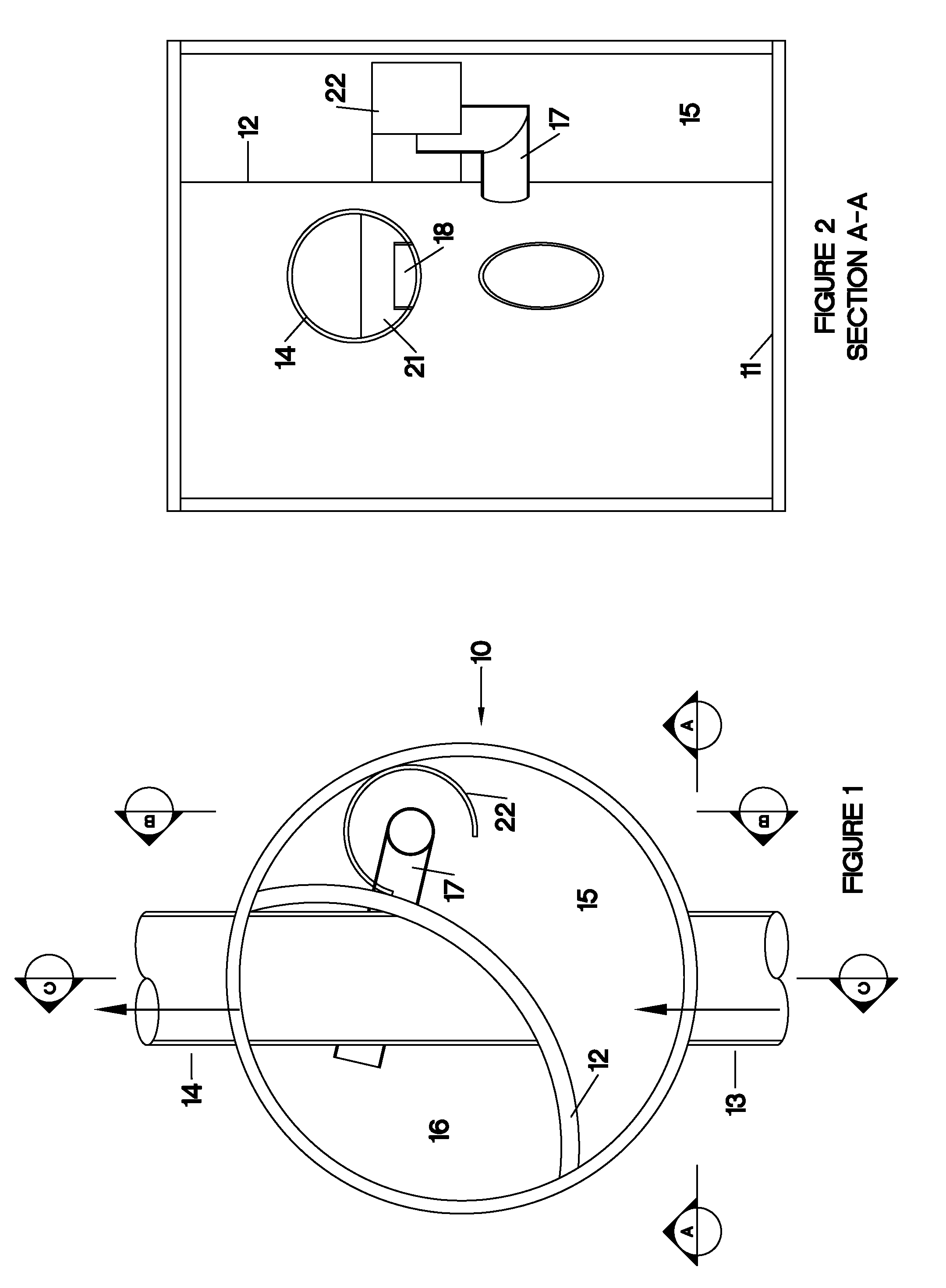
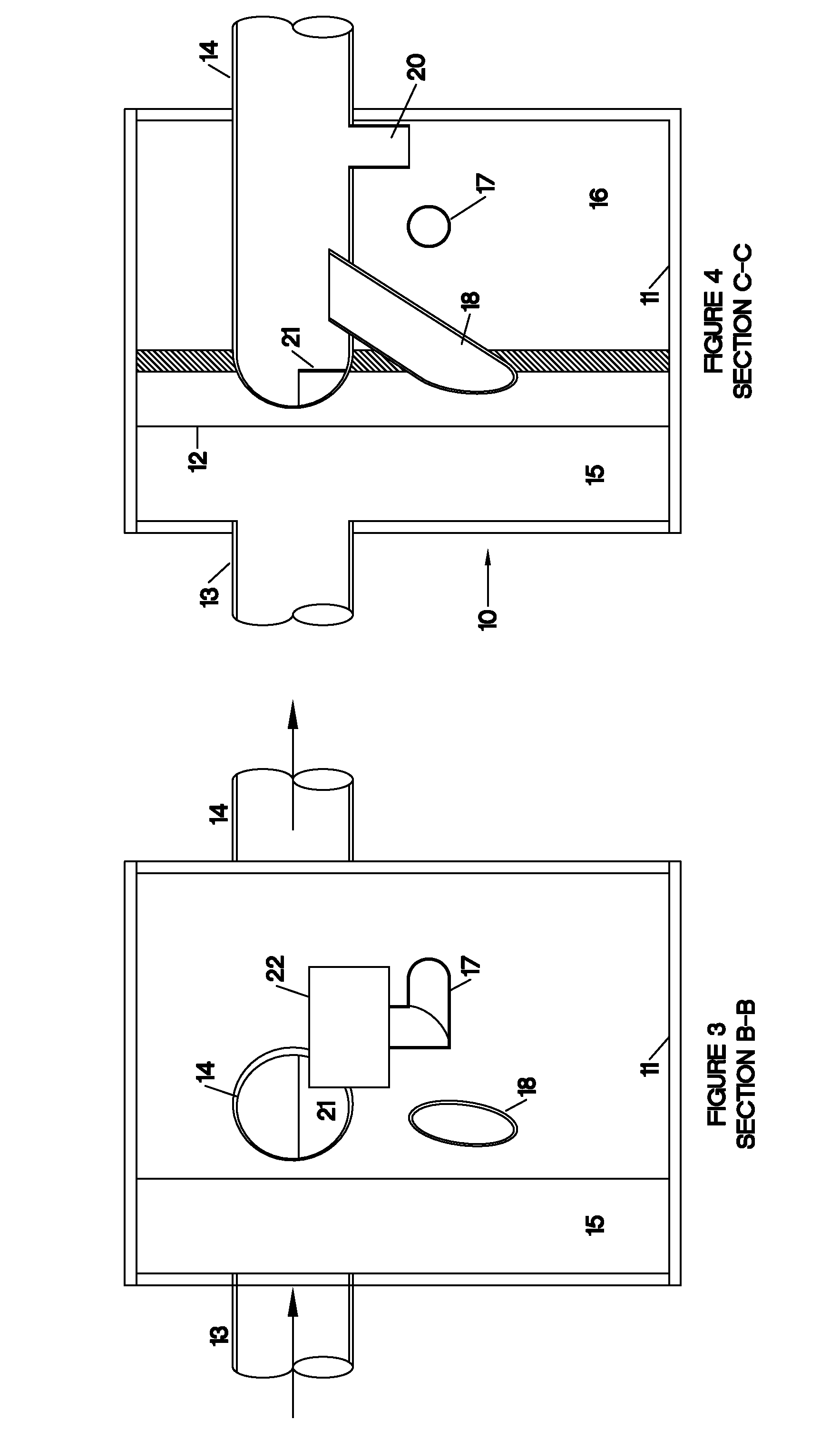
[0021]A first exemplary embodiment of the invention is illustrated in FIGS. 1-5. The flow separator is located within a cylindrical structure 10, which can be an independent structure or an existing standard cylindrical ground water structure. The structure 10 includes a floor 11 and an interior wall 12, which can be curved, as illustrated, or straight. The wall 12 divides the cylindrical structure 10 into two chambers, a primary chamber 15 and a storage / detainment chamber 16.

[0022]At least one inlet 13 and one outlet 14 are provided for intake and discharge of runoff water. The structure can have multiple inlets which can be located in the side or the top of the structure, however all inlets must initially discharge into chamber 15 of the structure. The structure may also have multiple outlets if placed downstream of the separation structure.

[0023]A first conduit, surface flow conduit 17 connects primary chamber 15 with storage chamber 16. Surface flow pipe 17 draws fluid from the ...


PUM

PropertyMeasurementUnit
elevationaaaaaaaaaa
elevationsaaaaaaaaaa
sizeaaaaaaaaaa

Abstract

Three flow paths within a single container are provided for the separation of contaminates, such as floating debris, heavy trash, lighter fluids and heavier fluids, from an effluent stream. A first flow path is provided for low flow conditions wherein the effluent stream pools in a first chamber within the container and the surface of the pooled fluid is drawn off, leaving heavy contaminates within the first chamber. The drawn fluid, with lighter and / or floating contaminates, enters a second chamber. The fluid is drawn from the second chamber below the surface level of the fluid, leaving the lighter and floating contaminates within the second chamber. In moderate flow conditions, a second flow path is established from the first chamber and out the container, bypassing the second chamber. Fluid for the second flow path is drawn from below the surface of the fluid in the first chamber to exclude light and floating contaminates. A third flow path is established when the first and second flow paths are insufficient to accommodate the effluent received by the container. The third flow path draws from the surface of the fluid in the first chamber and bypasses the second chamber in discharging from the container.

Description

REFERENCE TO RELATED CASES[0001]This application claims the benefits of U.S. Provisional applications Ser. No. 61 / 146,722 and 61 / 238,669 and 61 / 238,677.BACKGROUND OF THE INVENTION[0002]When it rains on a parking lot, a road, or other impervious surface, rain water will not permeate into the ground as it would if the surface were in its natural condition. The rain water will instead run off this surface often discharging directly into a stream or receiving body. Typically, some form of rain water collection and / or diversion is incorporated into the design of a paved surface of sufficient size to warrant storm water control. This results in an accumulation of the rain water prior to discharge into the watershed.[0003]Because impervious surfaces typically have been paved for a purpose, they will have vehicles, activity and / or traffic on them, which will cause an accumulation of pollutants between rain events. The rain water runoff therefore will include a the accumulated pollutants as ...

Claims


Application Information

Patent Timeline
Patent Type & Authority Patents(United States)
IPC IPC(8): B01D17/025B01D21/02E03F5/14B01D17/02B01D21/00C02F103/00E03F5/04
CPCB01D21/0012B01D21/02E03F1/00E03F5/0404B01D17/0211B01D21/003E03F5/14C02F2103/001E03F2201/10B01D2221/12E03F5/0403
Inventor PANK, THOMAS E.
Owner BAYSAVER TECH
Learn More