
Methods and apparatus for driving electro-optic displays

a technology of electro-optic displays and apparatus, applied in the direction of electric digital data processing, instruments, computing, etc., can solve the problems of inadequate service life of electro-optic displays, preventing their widespread use, and gas-based electrophoretic media being susceptible to the same types of problems

Inactive Publication Date: 2013-11-26
E INK CORPORATION
View PDF279 Cites 124 Cited by
  • Summary
  • Abstract
  • Description
  • Claims
  • Application Information

AI Technical Summary

Benefits of technology

[0087]In another aspect, this invention provides two related methods for reducing the unresponsive period when an electro-optic display is being updated. The first of these methods is for use in driving an electro-optic display having a plurality of pixels, each of which is capable of achieving at least two different gray levels, the method comprising:
[0105]Finally, this invention provides a method for reducing the amount of data which needs to be stored in order to drive an electro-optic display. Accordingly, this invention provides a method for driving an electro-optic display having a plurality of pixels, each of which is capable of achieving at least two different gray levels, the method comprising:

Problems solved by technology

Nevertheless, problems with the long-term image quality of these displays have prevented their widespread usage.
For example, particles that make up electrophoretic displays tend to settle, resulting in inadequate service-life for these displays.
Such gas-based electrophoretic media appear to be susceptible to the same types of problems due to particle settling as liquid-based electrophoretic media, when the media are used in an orientation which permits such settling, for example in a sign where the medium is disposed in a vertical plane.
Indeed, particle settling appears to be a more serious problem in gas-based electrophoretic media than in liquid-based ones, since the lower viscosity of gaseous fluids as compared with liquid ones allows more rapid settling of the electrophoretic particles.
However, inevitably there is some error in writing images on an impulse-driven display.
Other types of mechanical non-uniformity may arise from inevitable variations between different manufacturing batches of medium, manufacturing tolerances and materials variations.(f) Voltage Errors; The actual impulse applied to a pixel will inevitably differ slightly from that theoretically applied because of unavoidable slight errors in the voltages delivered by drivers.
General grayscale image flow suffers from an “accumulation of errors” phenomenon.
This accumulation of errors phenomenon applies not only to errors due to temperature, but also to errors of all the types listed above.
As described in the aforementioned 2003 / 0137521, compensating for such errors is possible, but only to a limited degree of precision.
For example, temperature errors can be compensated by using a temperature sensor and a lookup table, but the temperature sensor has a limited resolution and may read a temperature slightly different from that of the electro-optic medium.
Similarly, prior state dependence can be compensated by storing the prior states and using a multi-dimensional transition matrix, but controller memory limits the number of states that can be recorded and the size of the transition matrix that can be stored, placing a limit on the precision of this type of compensation.
Obviously, a pure general grayscale image flow drive scheme cannot rely upon using the optical rails to prevent errors in gray levels since in such a drive scheme any given pixel can undergo an infinitely large number of changes in gray level without ever touching either optical rail.
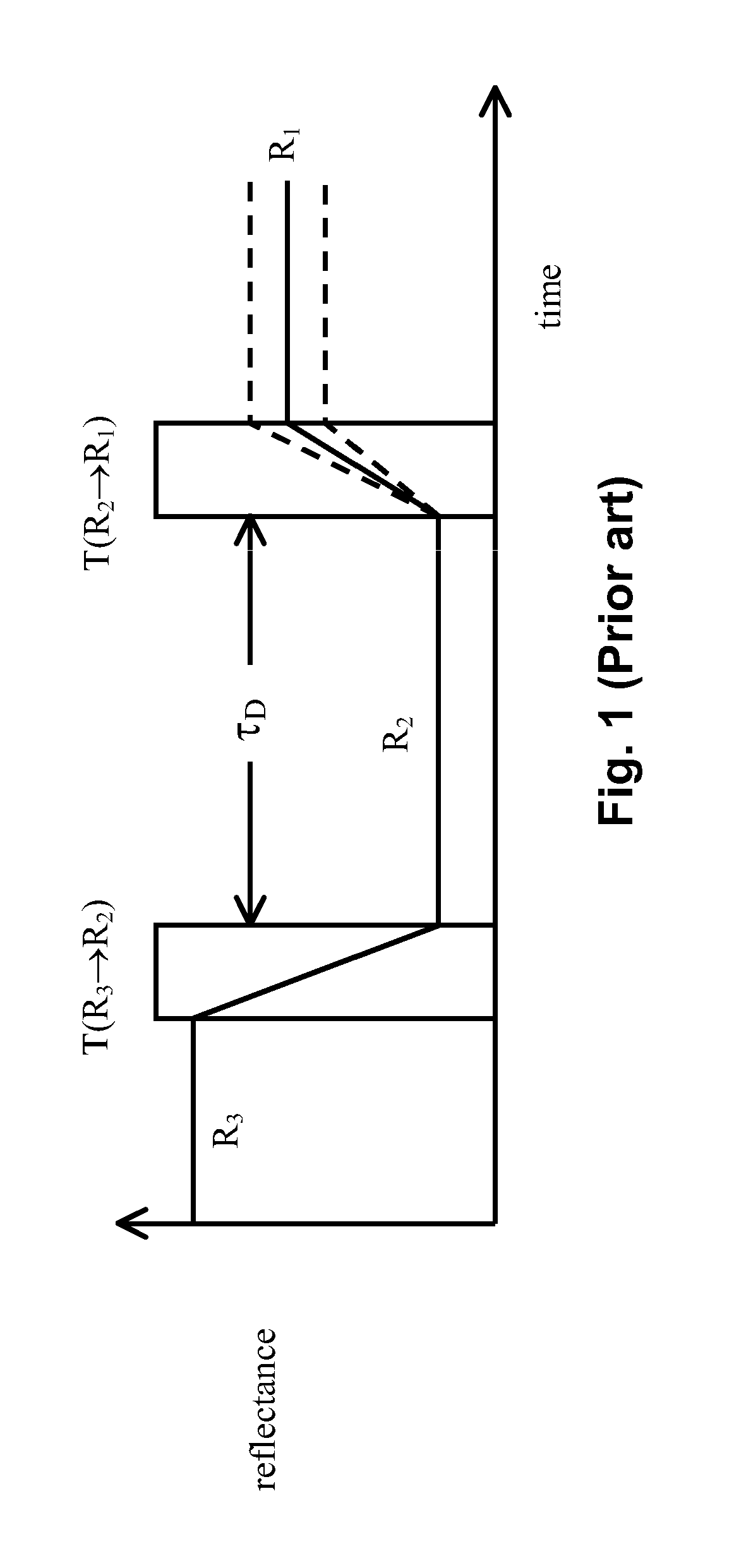
Although these problems can be reduced or overcome by driving all pixels of the display to one of the extreme states for a substantial period before driving the required pixels to other states, the resultant “flash” of solid color is often unacceptable; for example, a reader of an electronic book may desire the text of the book to scroll down the screen, and may be distracted, or lose his place, if the display is required to flash solid black or white at frequent intervals.
Furthermore, such flashing of the display increases its energy consumption and may reduce the working lifetime of the display.
However, such DTC may conflict with other desirable properties of drive schemes.
Optical errors can arise from DTD of a display.
The problem with this approach to DTC of a drive scheme is that the drive scheme as a whole is no longer DC balanced.
Repeating this loop causes a build-up of DC imbalance, which can be detrimental to the performance of the display.
However, in most of the aforementioned methods and controllers, the updating operation is “atomic” in the sense that once an update is started, the memory cannot accept any new image data until the update is complete.
This causes difficulties when it is desired to use the display for applications that accept user input, for example via a keyboard or similar data input device, since the controller is not responsive to user input while an update is being effected.
It is known to use structures already developed for gray scale image displays to reduce the unresponsive period by up to 65 percent, as compared with prior art methods and controllers, with only modest increases in the complexity and memory requirements of the controller.

Method used


Image

  • Methods and apparatus for driving electro-optic displays
  • Methods and apparatus for driving electro-optic displays
  • Methods and apparatus for driving electro-optic displays

Examples


Embodiment Construction

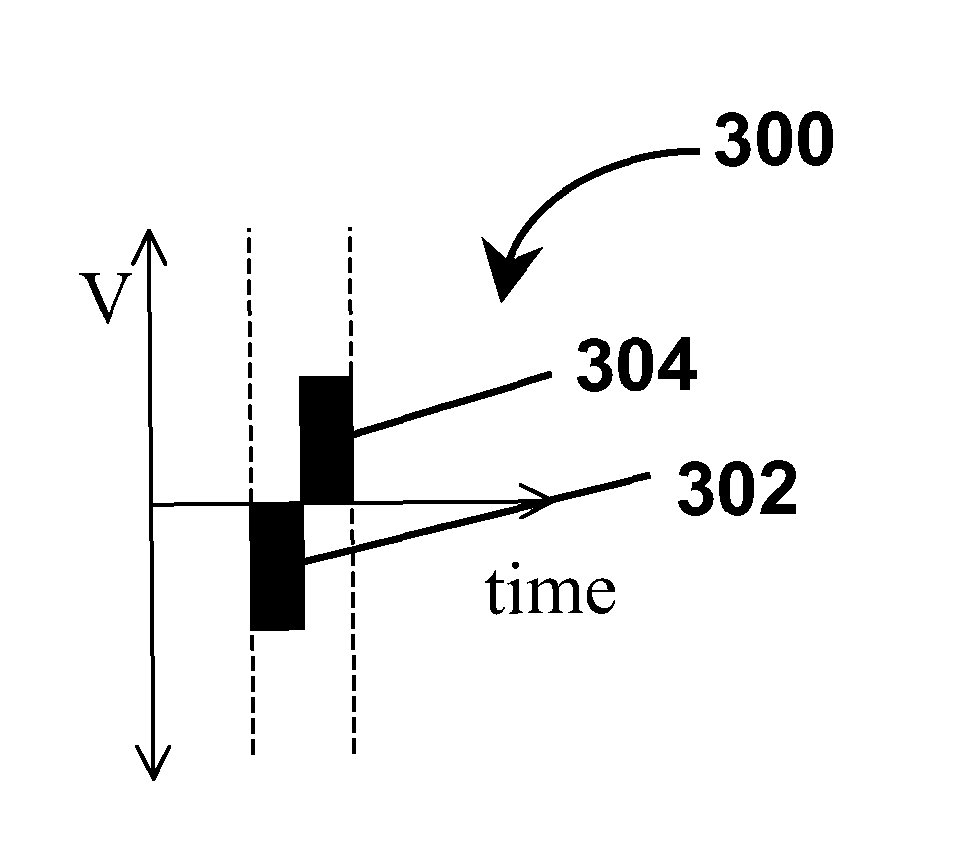
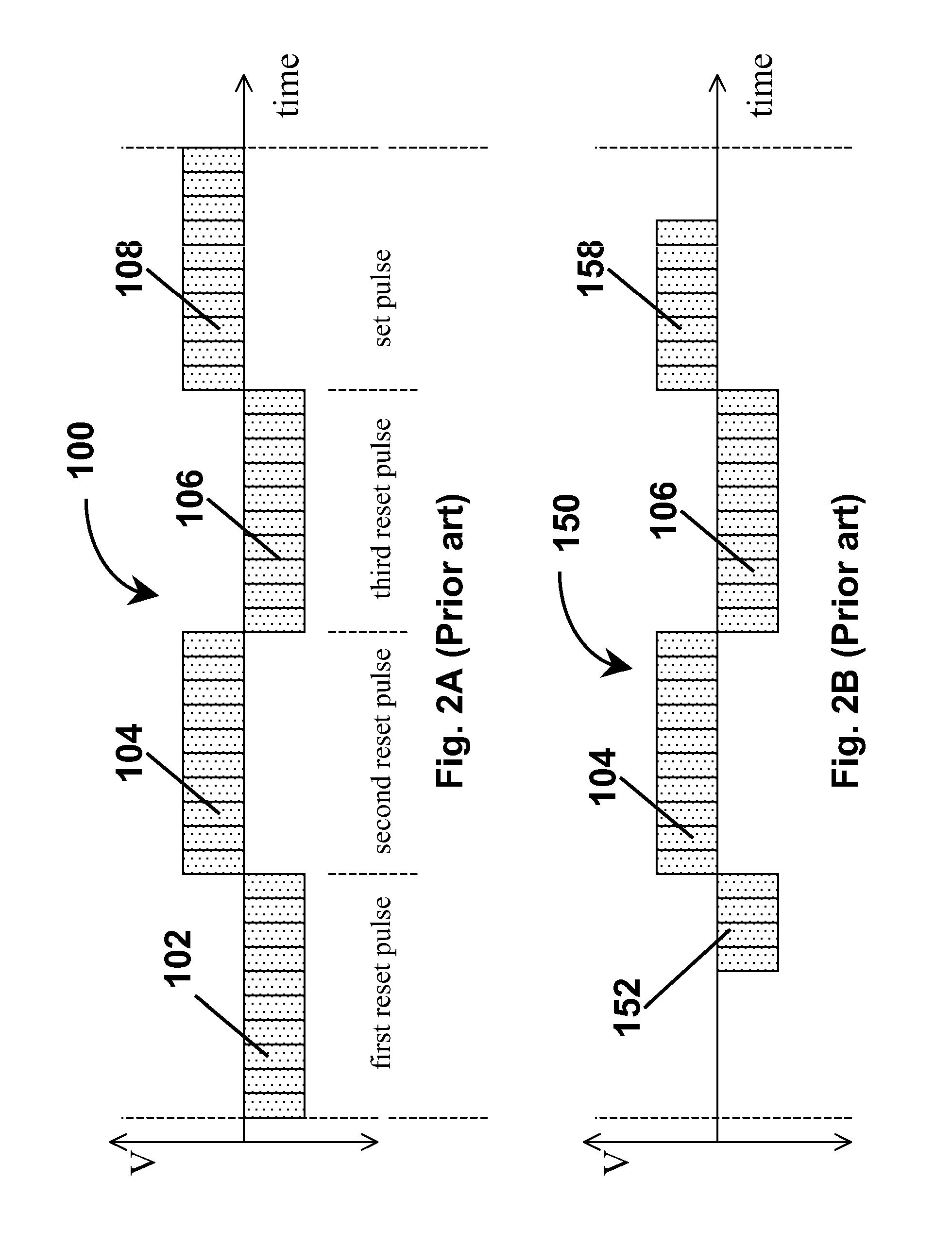
[0141]From the foregoing Summary, it will be seen that the present invention provides a number of differing methods for driving electro-optic displays, especially bistable electro-optic displays, and apparatus and software code adapted to carry out such methods. The various methods of the invention will mainly be described separately below, but it should be understood that a single electro-optic display, or component thereof, may make use of more than one aspect of the present invention. For example, a single electro-optic display might make use of the BPPSS, IMP and DTCBPP aspects of the present invention. It should also be noted that the preferred forms of balanced pulse pairs are common to all aspects of the present invention which make use of such pulse pairs, as are the preferred limitations on the sizes of such pulse pairs and the methods for adjusting the length of waveforms to accommodate insertion or excision of such pairs and / or periods of zero voltage. Finally, it should ...


PUM

PropertyMeasurementUnit
reflectanceaaaaaaaaaa
timeaaaaaaaaaa

Abstract

Waveforms for driving electro-optic displays, especially bistable electro-optic displays, are modified by one or more of insertion of at least one balanced pulse pair into a base waveform; excision of at least one balanced pulse pair from the base waveform; and insertion of at least one period of zero voltage into the base waveform. Such modifications permit fine control of gray levels.

Description

REFERENCE TO RELATED APPLICATIONS[0001]This application is a division of copending application Ser. No. 11 / 161,715, filed Aug. 13, 2005 (Publication No. 2005 / 0280626), which claims benefit of the following provisional Applications: (a) Application Ser. No. 60 / 601,242, filed Aug. 13, 2004; (b) Application Ser. No. 60 / 522,372, filed Sep. 21, 2004; and (c) Application Ser. No. 60 / 522,393, filed Sep. 24, 2004.[0002]The aforementioned copending application Ser. No. 11 / 161,715 is also a continuation-in-part of application Ser. No. 10 / 904,707, filed Nov. 24, 2004 (Publication No. 2005 / 0179642), which itself claims benefit of provisional Application Ser. Nos. 60 / 481,711 and 60 / 481,713, both filed Nov. 26, 2003.[0003]The aforementioned application Ser. No. 10 / 904,707 is a continuation-in-part of application Ser. No. 10 / 879,335, filed Jun. 29, 2004 (Publication No. 2005 / 0024353, now U.S. Pat. No. 7,528,822, issued May 5, 2009), which claims benefit of the following provisional Applications: S...

Claims


Application Information

Patent Timeline
Patent Type & Authority Patents(United States)
IPC IPC(8): G09G3/34G02F1/167
CPCG09G5/00G09G3/344G02F1/167G02F1/13306G09G3/2018G09G2310/061G09G2310/068
Inventor AMUNDSON, KARL R.ZEHNER, ROBERT W.SJODIN, THEODORE A.
Owner E INK CORPORATION
Learn More