
Short-range photographic light source module for use in image capture device and image capture device provided with same

a technology of light source module and image capture device, which is applied in the field of short-range photographic light source module, can solve the problems of difficult control of light exposure, inability to effectively analyze or verify captured images, and inability to identify the resulted image, so as to increase the quality of captured images and block interferen

Inactive Publication Date: 2013-11-26
LUMOS TECH
View PDF6 Cites 4 Cited by
  • Summary
  • Abstract
  • Description
  • Claims
  • Application Information

AI Technical Summary

Benefits of technology

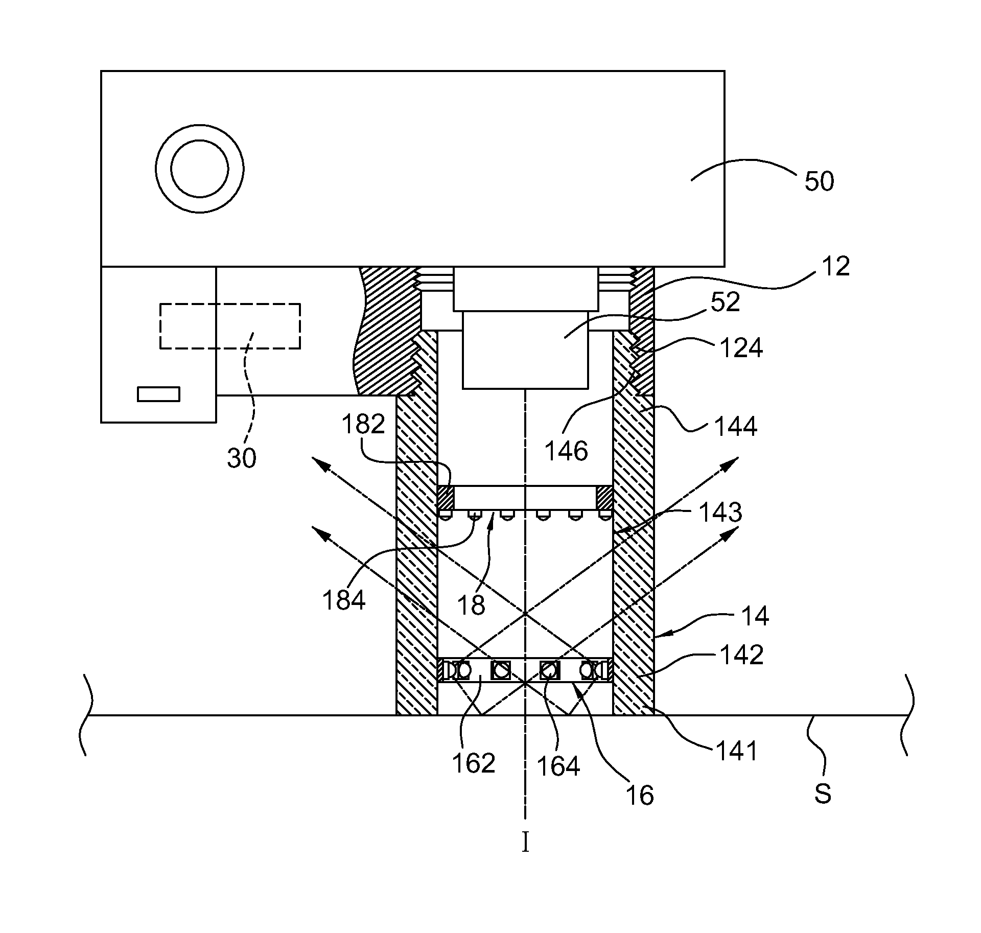
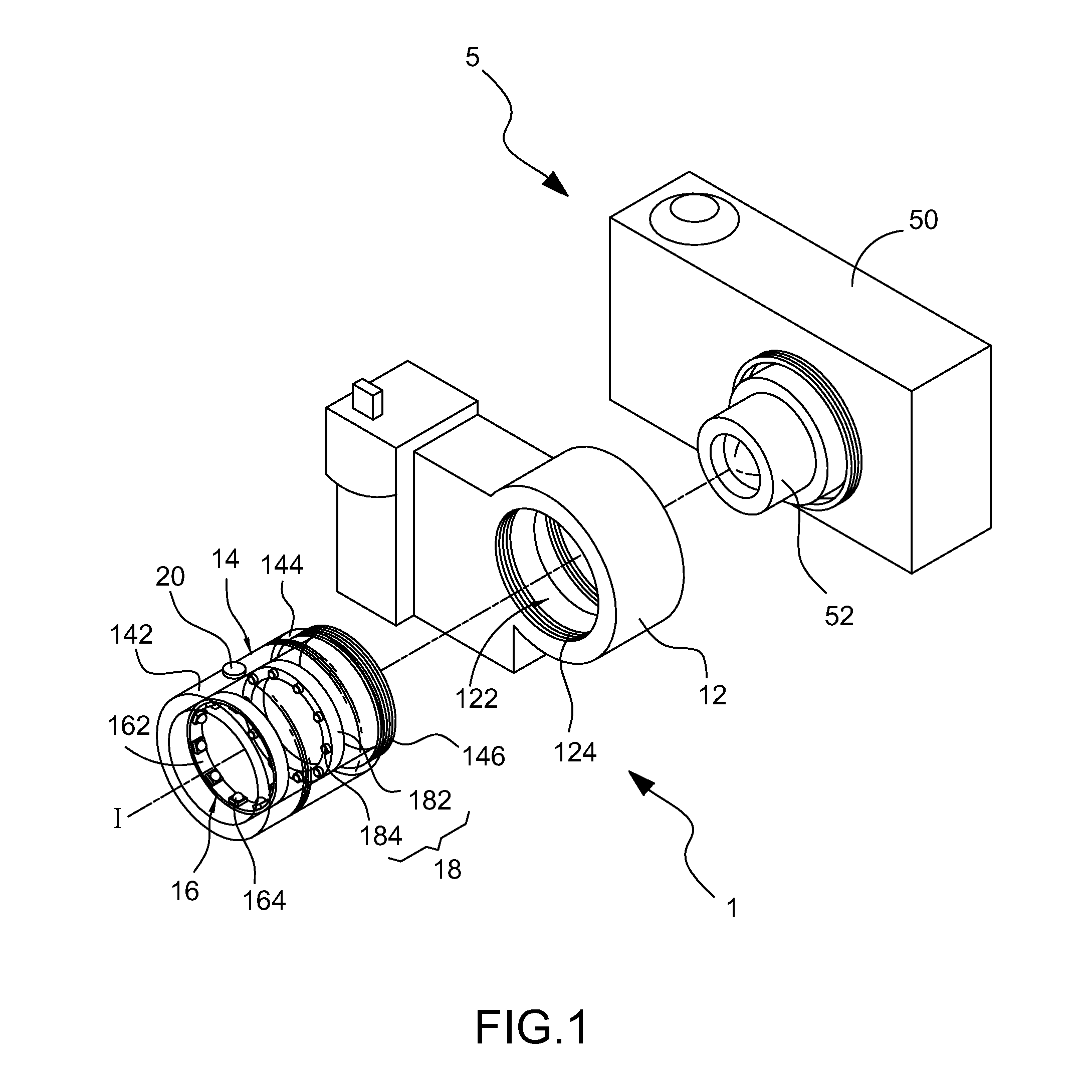
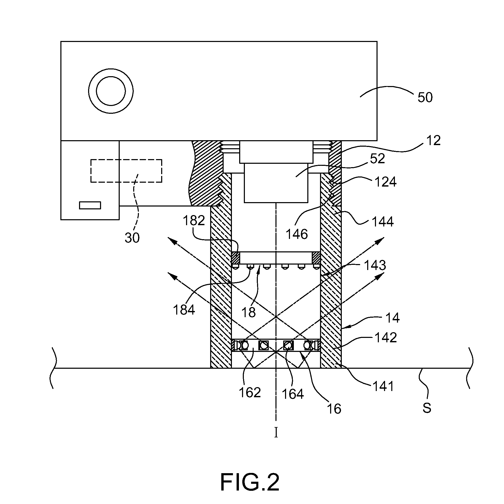
[0008]An objective of the invention is to provide a short-range photographic light source module having a light shield portion which can block out the interference caused by intensive ambient light and stray light, thereby increasing the quality of the captured images.
[0010]Still another objective of the invention is to provide a short-range photographic light source module having ring-wisely configured illuminating units so as to provide uniform light supplementation on a target object at a close distance thereby improving the imaging quality of the object.
[0011]Yet another objective of the invention is to provide a short-range photographic light source module having illuminating units with different light-emitting directions, so as to allow choices of light supplementation angle conforming to actual requirements of the target object as well as the photographic environment.
[0012]Yet still another objective of the invention is to provide an image capture device provided with the short-range photographic light source module disclosed herein, wherein the short-range photographic light source module includes a light shield portion which can block out the interference caused by intensive ambient light and stray light, thereby increasing the quality of the captured images.
[0013]Further still another objective of the invention is to provide an image capture device provided with the short-range photographic light source module disclosed herein, which allows the photographer to freely select the light sources and illumination angles required for the target object and the photographic environment, thereby improving the convenience and application flexibility of photography.
[0018]In summary, by installing the short-range photographic light source module disclosed herein onto the image capture device, it is possible to, on one hand, take short-range images, and, on the other hand, further adjust the light supplementation angle such that the target object can be accurately light supplemented to obtain the best photographic effect. In particular, it permits the user to selectively use one or both of the two illuminating units based on the characteristics of the target object, thereby greatly increasing convenience in use to achieve the aforementioned objectives.

Problems solved by technology

Apparently, if the aperture is adjusted to be smaller, the intensity of light would get lower, resulting in darkness of the captured images which cannot be effectively analyzed or verified.
Unfortunately, in the case where the target object slightly moves or the image capture device itself sways during the shutter open time, the resulted image would become obscure or even completely unidentifiable.
Especially, for short-range photography, the control of exposure to light is very challenging and tends to cause the over-exposure or under-exposure problems.
In such case, the pictures taken in this way may appear awkward and unnatural.
Furthermore, for specific target objects, such as a fingerprint left on a glass plate, light emitted by the flashlight and directly reflected from the glass plate may be much brighter than the fingerprint image itself and, thus, may entirely hinder the weak diffusion light from the fingerprint.
Besides, for example, during an operation of searching for blood traces splashed on the ground in an area of intensive sunlight, the attempt to effectively identify the fluorescent reaction of blood traces by using a ultra-violet (UV) light source may fail due to strong UV emission in sunlight which seriously deteriorates the quality of images.
This not only forces the user to prepare two different types of light sources at the same time, but causes alignment problem in the captured picture due to light source alternations during a photographic operation.

Method used


Image

  • Short-range photographic light source module for use in image capture device and image capture device provided with same
  • Short-range photographic light source module for use in image capture device and image capture device provided with same
  • Short-range photographic light source module for use in image capture device and image capture device provided with same

Examples


second embodiment

[0037]Now Referring to FIG. 3, there is shown the invention, in which the front end portion 142 is threadedly engaged with the rear end portion 144. According to this embodiment, the length of the sleeve tube 14 is adjustable by threadedly moving the front end portion 142 back and forth with respect to the rear end portion 144 along the central axis I. When the distance between the image capture device 5 and the target object should be changed in accordance with actual optical parameters of the image capture device 5, the overall length of the sleeve tube 14 can be conveniently adjusted by rotating the front end portion 142 in relation to the rear end portion 144.

third embodiment

[0038]Referring to FIG. 4, there is shown a short-range photographic light source module 1 according to the invention, in which the sleeve tube 14 is directly adapted to the imaging lens 52 of the device body 50 in the absence of a adapter base. Electrical power is supplied to the first illuminating unit 16 and the second illuminating unit 18 from a power source mounted in the device body 50.

fourth embodiment

[0039]Referring to FIG. 5, there is shown the invention, in which the power source unit 30 is exemplified as a battery box mounted atop the device body 50 of the image capture device 5 and electrically connected to the short-range photographic light source module1 through an external transmission wire 31 to activate the illuminating units for lighting.


PUM


Abstract

The invention provides a short-range photographic light source module for use in an image capture device and the image capture device provided with the same. The image capture device comprises an imaging lens having a light axis. The short-range photographic light source module is mounted in correspondence at the imaging lens to serve as a light source when the image capture device is capturing an image of a target object at a short range. The module further includes a sleeve tube having a rear end portion, a front end portion, an interior side connecting the front end portion to the rear end portion, a light shield portion, and a first illuminating unit and a second illuminating unit.

Description

BACKGROUND OF THE INVENTION[0001]1. Field of the Invention[0002]The present invention relates to a short-range photographic light source module and, more particularly, to a short-range photographic light source module for use in an image capture device.[0003]2. Description of Related Art[0004]The macro photography refers to a photographic mode for capturing an image of a short-range object or a very tiny object, typically produced at a reproduction ratio ranging from 1:1 to 1:4. Herein the ratio “1:4” means that the image size thus produced is a quarter of the actual object size. By reaching a reproduction ratio of 1:1, the actual size of the target object can be completely captured and presented. From the aspect of application, in addition to conventional applications in ecological observation and scientific research, the technique of macro photography can be more comprehensively utilized in various fields, including medical cosmetic surgery, criminal identification or anti-counter...

Claims


Application Information

Patent Timeline
Patent Type & Authority Patents(United States)
IPC IPC(8): G03B15/06G03B15/02H04N5/222
CPCG03B15/05G03B17/566G03B2215/0539G03B2215/056G03B2215/0567
Inventor YANG, CHIH-YI
Owner LUMOS TECH
Learn More