Assembly for armoring an amphibious vehicle against projectile penetrations

a technology for amphibious vehicles and projectiles, applied in the field of motorized amphibious vehicles, can solve the problems of affecting the normal acceptance of adding armor to military land vehicles, affecting the performance of amphibious vehicles upon water use, and affecting the performance of amphibious vehicles, etc., to achieve the effect of maximizing water buoyancy, increasing the ability of sheets to fragment and impinge projectiles, and high hardness to weight ratio

Active Publication Date: 2013-12-03
LEADING TECH COMPOSITES
View PDF2 Cites 32 Cited by
  • Summary
  • Abstract
  • Description
  • Claims
  • Application Information

AI Technical Summary

Benefits of technology

[0005]A first structural component of the instant inventive assembly for armoring an amphibious vehicle against ballistic projectile attacks and penetrations comprises a rigid projectile strike face sheet having a thickness, an inner surface, and an outer surface. In a preferred embodiment of the instant invention, the rigid strike face sheet comprises a hard and durable ceramic material such as boron carbide ceramic, silicone carbide ceramic or aluminum oxide ceramic. Suitably, the strike face sheet material may comprise a hardened aluminum alloy. Also, suitably, the strike face material may comprise ballistic steel or rolled homogeneous steel armor. Of such materials, the most desirable are those with relatively high hardness to weight ratio for increasing the sheet's ability to fragment impinging projectiles while maximizing buoyancy in water. The thickness of the ballistic strike face material may suitably be increased or decreased in accordance with the level of the ballistic projectile threat present in environments within which the inventive assembly is to be utilized.
[0006]A further structural component of the instant inventive amphibious vehicle armoring assembly comprises a relatively thick buoyant sheet which is preferably co-planar or co-extensive with and is fixedly mounted or attached at a position inwardly from the rigid strike face sheet. In a preferred embodiment of the instant inventive assembly, the buoyant sheet is composed of a low density and non-absorbent material. The low density character of the buoyant sheet allows the stratum to effectively counter the typically high density and non-buoyant character of the overlying ballistic strike face sheet. The preferred non-absorbent character of the buoyant sheet advantageously protects from water absorption and “water logging” of the thickened buoyant stratum. In a preferred embodiment, the low density non-absorbent material comprises a matrix of hardened or substantially rigid foam material such as polyisocyanurate foam, polyvinyl chloride foam, polystyrene foam, phenolic foam, polyurea foam, or aluminum foam. Preferably, the thickness of the buoyant stratum is at least as great as that of the ballistic strike face stratum. In operation, the buoyant stratum advantageously dually functions for buoyancy enhancement and for projectile spall distribution.
[0009]In use of the instant inventive assembly for armoring an amphibious vehicle, an amphibious vehicle bearing such armoring assembly may enter a river or lake for amphibious operations and, as a result of additional flotation provided by the buoyant layer, the vehicle maintains a water line or floating level within the water which is substantially the same as that maintained by a similar but unarmored amphibious vehicle. Thus, the vehicle's load carrying capacity remains substantially unaltered by the installation of the inventive armoring assembly. Upon experiencing a projectile attack, the buoyant layer of the armoring assembly advantageously further functions to provide a projectile spall dispersion zone which minimizes the possibility that projectile spall fragments generated by the strike face will reach the hull with sufficient concentration to penetrate the amphibious vehicle's hull.

Problems solved by technology

However, the typical acceptability of addition of armor to military land vehicles is not equally experienced when the vehicle is adapted for amphibious operations.
While military amphibious vehicles, like military land vehicles, are typically capable of carrying very heavy exterior armor during land based operations, such armor often undesirably detracts from and degrades the performance of amphibious vehicles during use upon the water.
Such degradation of performance may arise as the result of the typically high density relative to water of applied cladding layers of armoring materials.
As a result, installation of outer cladding armor over the hull of an amphibious military vehicle degrades the vehicle's capacity for carrying troops and cargo.

Method used


Image

  • Assembly for armoring an amphibious vehicle against projectile penetrations
  • Assembly for armoring an amphibious vehicle against projectile penetrations
  • Assembly for armoring an amphibious vehicle against projectile penetrations

Examples


Embodiment Construction

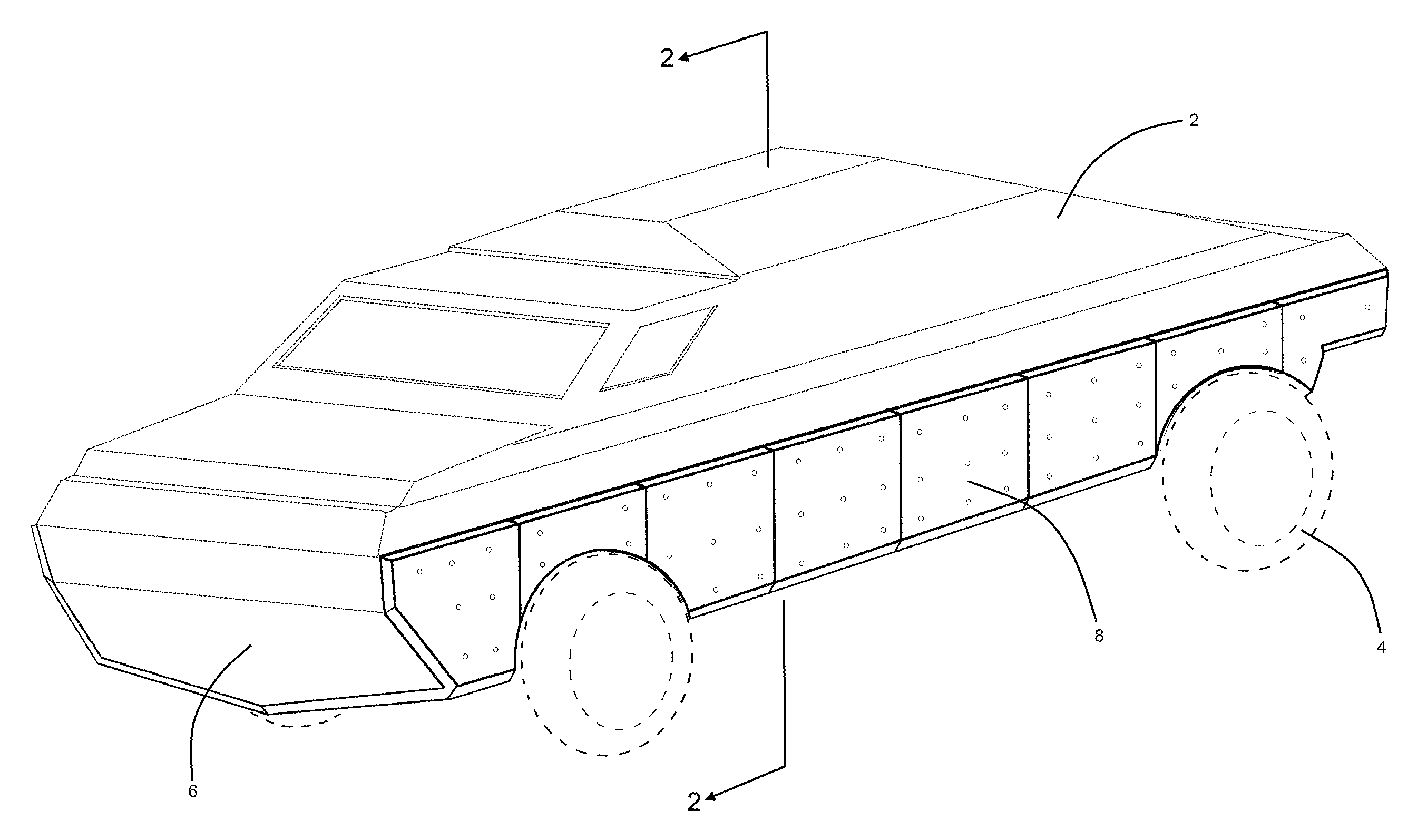
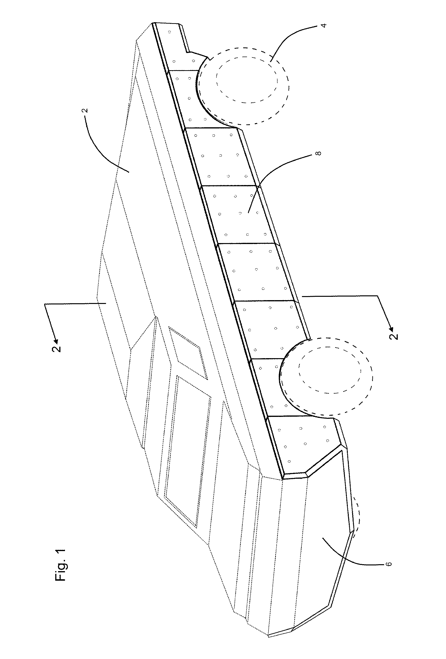
[0016]Referring now to the drawings, and in particular to FIG. 1, a military amphibious vehicle 2 has a steel hull wall 6 that extends from the vehicle's bow to stern and from its starboard side to port. For use in land operations, the vehicle 2 has powered wheels 4. Alternatively, for use in water operations, the vehicle typically has an engine driven stern mounted water propulsion drive (not within view) such as an exposed propellor or a steerable water jet nozzle.

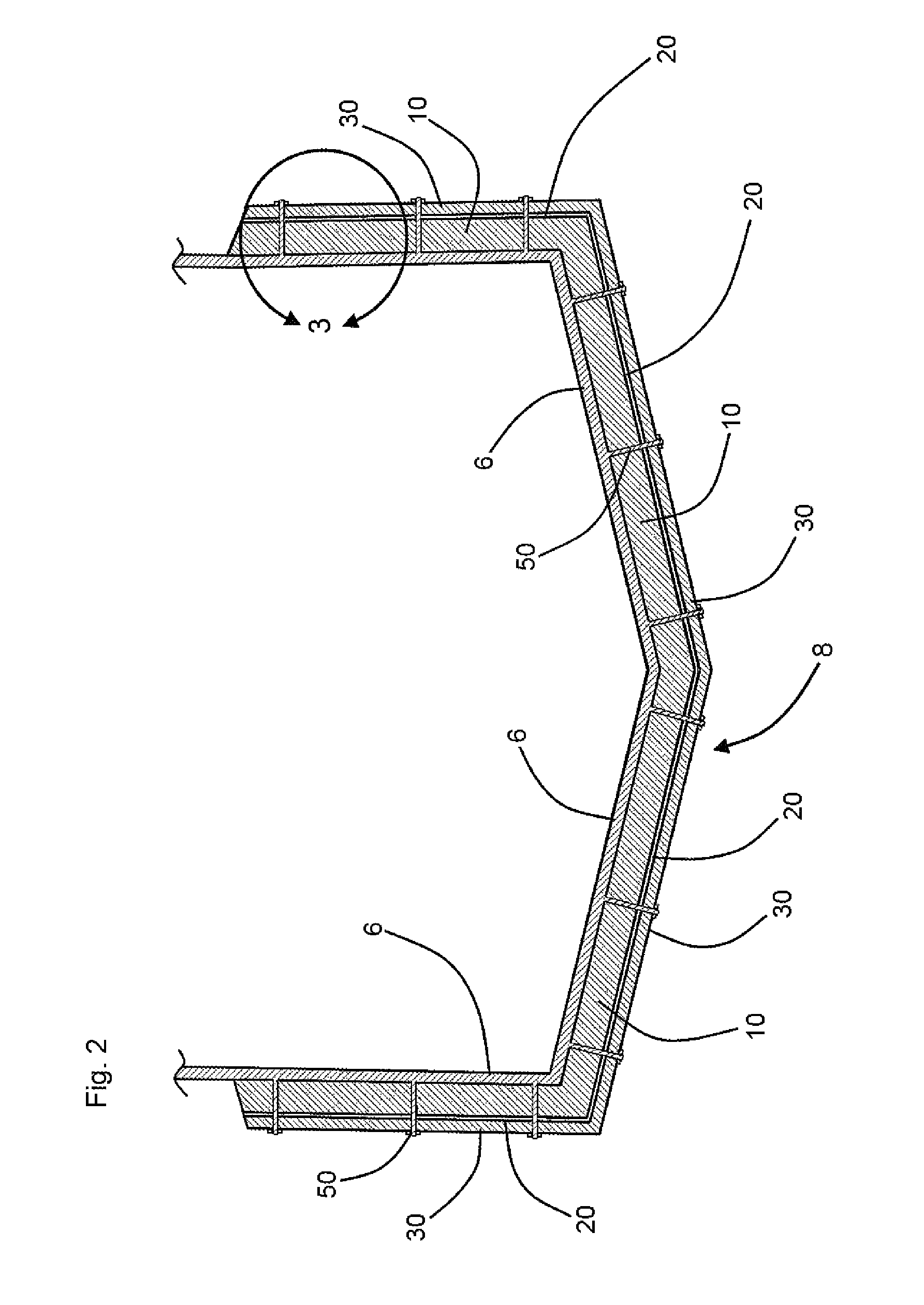
[0017]Referring further to FIG. 1, an exterior armoring strata 8 is securely mounted over the starboard and port sides of the vehicle's hull 6, and such armoring strata extends over the undersurfaces of the hull 6 from the vehicle's bow end to its stern. Referring further simultaneously to FIGS. 2 and 3, the armoring strata 8 comprises a relatively thick buoyant sheet 10. As depicted, the buoyant sheet 10 is approximately twenty millimeters thick. The buoyant sheet 10 preferably comprises a hardened and water resistant o...


PUM


Abstract

An assembly for armoring an amphibious vehicle against projectile penetrations, the amphibious vehicle having a hull, the assembly including a rigid spall generating sheet, the rigid spall generating sheet having a thickness and an outer surface; a buoyant sheet fixedly attached to and extending inwardly from the rigid spall generating sheet; and a multiplicity of fasteners interconnecting the rigid and buoyant sheets with the amphibious vehicle's hull, the buoyant sheet incorporating a low density, nonabsorbent hardened foam material; the buoyant sheet functioning for vehicle buoyancy enhancement and for defining a spall dispersal space overlying the hull and underlying the rigid spall generating sheet.

Description

FIELD OF THE INVENTION[0001]This invention relates to motorized amphibious vehicles. More particularly this invention relates to adaptations of such vehicles wherein such vehicles are armored or protected against ballistic projectile attacks.BACKGROUND OF THE INVENTION[0002]Heavy military vehicles such as military transport trucks and troop carriers typically incorporate massive steel chassis and suspension components, and such vehicles typically have powerful engines. Where such vehicles are used for ground operations within hostile territories which present a risk of ballistic projectile attack, such vehicles are known to be protectively adapted to include an outer cladding or covering of heavy ballistic armoring material. The installation of such outer protective stratums upon such heavy military vehicles typically results in no unacceptable degradation of the performance of the vehicle. However, the typical acceptability of addition of armor to military land vehicles is not equa...

Claims


Application Information

Patent Timeline
Patent Type & Authority Patents(United States)
IPC IPC(8): F41H5/04F41H7/00B60F3/00
CPCB60F3/0038F41H5/013F41H7/02F41H7/042
Inventor COLTRANE, MICHAEL D.
Owner LEADING TECH COMPOSITES
Why Eureka
Try Eureka