
Trailer coupling

a technology of trailer coupling and trailer, which is applied in the direction of couplings, towed devices, basic electric elements, etc., can solve the problems of increasing the own weight and the required space of the known trailer coupling, reducing the maximum possible swivel angle between the trailer coupling and the trailer-side coupling element, and hardly achieving the minimum swivel angle, for example 20°, etc., to achieve the effect of reducing the required space, reducing

Inactive Publication Date: 2013-12-03
SCHARMULLER JOSEF +1
View PDF16 Cites 8 Cited by
  • Summary
  • Abstract
  • Description
  • Claims
  • Application Information

AI Technical Summary

Benefits of technology

The invention is a trailer coupling that can withstand high force loads, takes up minimal space, and is efficient in weight. It also allows for a large swivel angle, resulting in a compact design and the ability to safely tow trailers.

Problems solved by technology

Oftentimes, known trailer couplings have to be reinforced, i.e. they have to be built larger and with more material which disadvantageously leads to an increase of the own weight and the required space of the known trailer coupling.
A further disadvantage when using this reinforcement of the trailer coupling can be that the maximal possible swivel angle between the trailer coupling and the trailer-side coupling element is decreased and, if applicable, a legally mandated minimal swivel angle, for example 20°, is hardly achieved.

Method used


Image

  • Trailer coupling
  • Trailer coupling
  • Trailer coupling

Examples


first embodiment

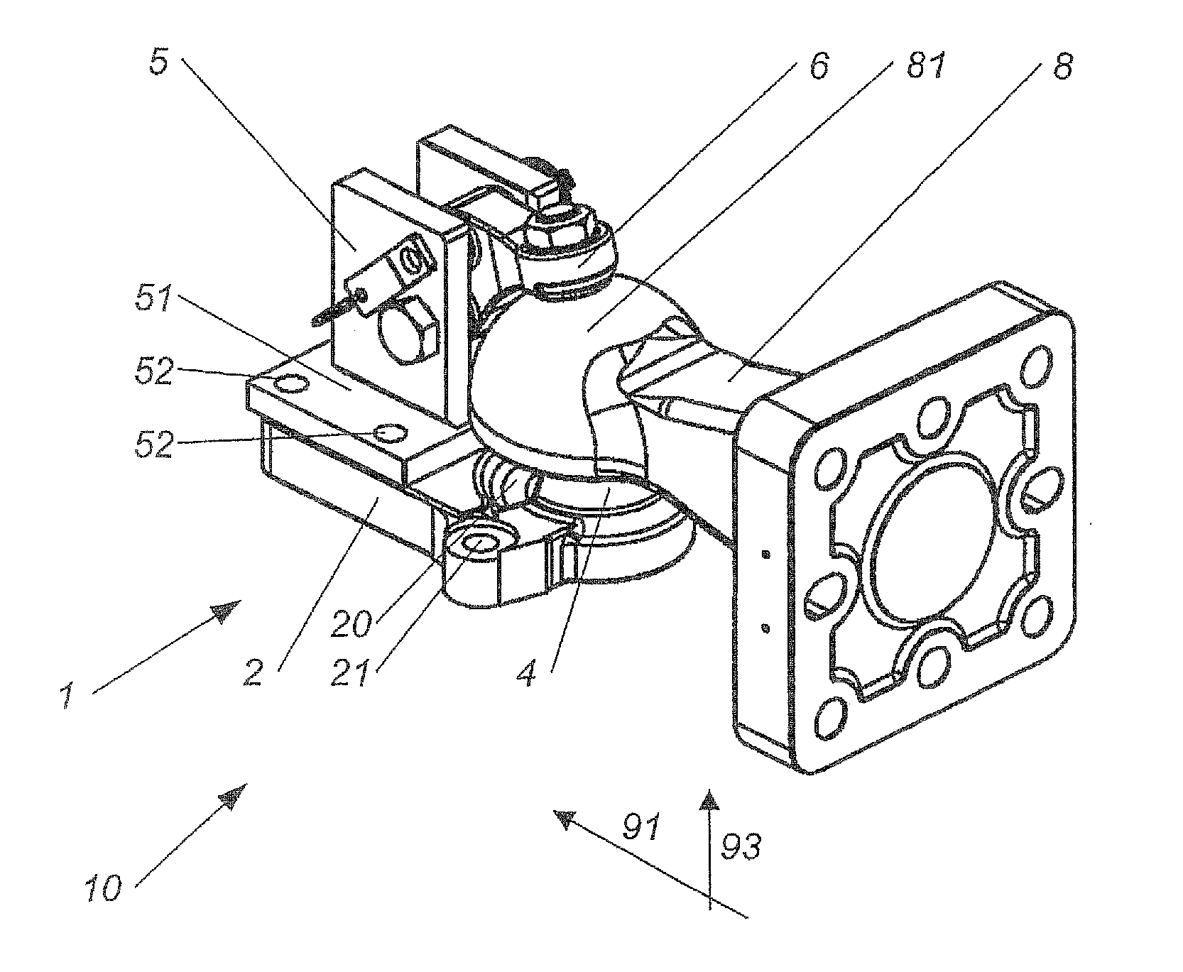
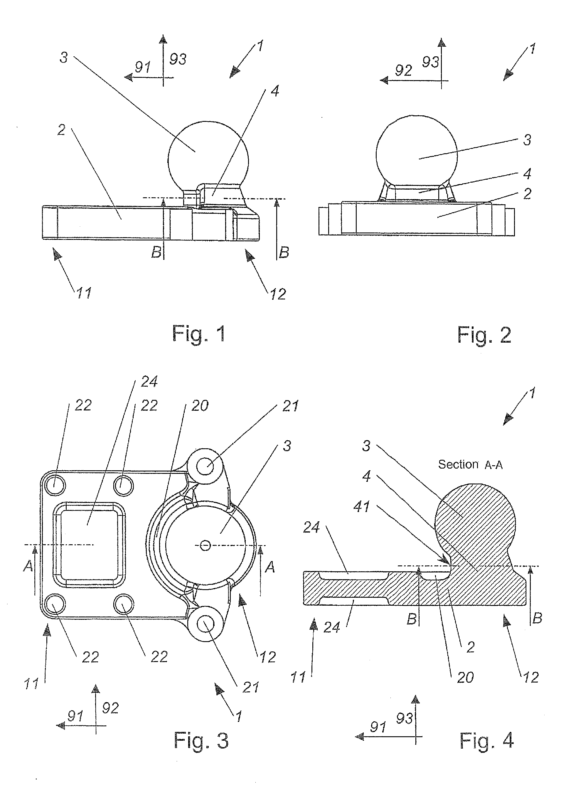
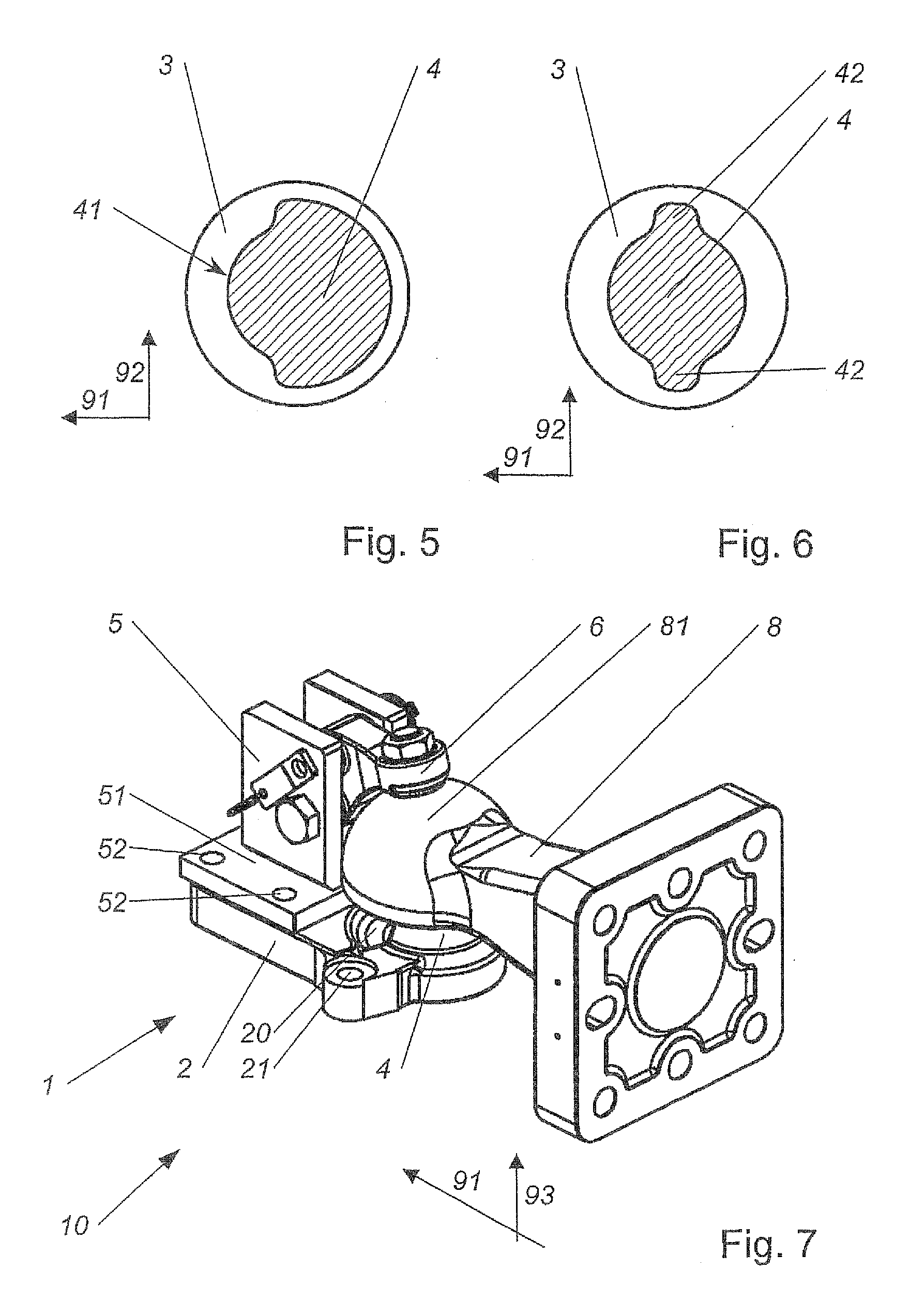
[0037]In this connection, the cut-away part of the circular cross section can be disposed at the border of the neck 4, which border points in the first direction 91 as already provided in the trailer coupling 1. This has the advantage that the swivel angle can be especially large in upward direction for example over 30°, i.e. when the trailer-side towing element is swiveled upwards. At the border of the neck 4 which points into the first direction 91, the outer surface of the neck 4 is, at least in areas directed in the first direction 91.

second embodiment

[0038]As provided for example in the trailer coupling 1, in an advantageous refinement of the invention, the cross section of the neck 4 can essentially correspond to a circular cross section, in which protuberances 42 are formed in the second direction 92. This advantageous geometry of the neck 4 is shown in FIG. 6. This has the advantage that the swivel angle can be particularly large in upward and downward direction, for example above 30°.

[0039]The neck length extends between the hitch ball 3 and the flange plate 2. The neck length extends from the transition of the conically shaped surface of the hitch ball 3 to the neck 4 up to the transition of the neck 4 to the flange plate 2. The transitions can be formed rounded. Here, the neck length extends approximately up to the middle of the rounded transitions. Particularly advantageously, the neck length can be less than the diameter, in particular less than the radius, of the hitch ball 3. Particularly advantageously, the neck lengt...


PUM


Abstract

The invention relates to a trailer coupling (1) for fastening to a towing vehicle, having a flange plate (2) and a hitch ball (3), wherein a neck (4) that connects the flange plate (2) and the hitch ball (3) is formed. For a high force load capacity, small installation space requirements, weight efficient constructability and assurance of large swivel angles, it is suggested, that the maximal extent of the neck (4) in a first direction (91) is smaller than in a second direction (92), which is normal to the first direction (91).

Description

CROSS-REFERENCES TO RELATED APPLICATIONS[0001]This application is the U.S. National Stage of International Application No. PCT / AT2010 / 000180, filed May 21, 2010, which designated the United States and has been published as International Publication No. WO 2010 / 144927 and which claims the priority of Austrian Patent Application, Serial No. A 924 / 2009, filed Jun. 16, 2009, pursuant to 35 U.S.C. 119(a)-(d).BACKGROUND OF THE INVENTION[0002]The invention relates to a trailer coupling. The trailer coupling—together with a trailer-side coupling element—is provided for forming a towing device that can be coupled. The trailer coupling represents the towing-device-side part, and the trailer-side coupling element represents the trailer-side part of the towing device.[0003]Known trailer couplings embrace the hitch ball. The trailer coupling is mounted on the towing vehicle, for example by bolting. The hitch ball is fixed in position relative to the towing vehicle. For coupling of the trailer to...

Claims


Application Information

Patent Timeline
Patent Type & Authority Patents(United States)
IPC IPC(8): B60D1/06B60D1/28
CPCB60D1/06B60D1/28B60D1/583B60D1/52Y10T403/32647
Inventor SCHARMULLER, JOSEFSCHARMULLER, JR., JOSEF
Owner SCHARMULLER JOSEF
Learn More