Light-emitting device and electronic device using the light-emitting device

a technology which is applied in the field of light-emitting devices and electronic devices using light-emitting devices, can solve the problems of light-emitting elements being damaged and separated, and achieve the effect of reducing weight and keeping the distance between the substrates almost constan

Active Publication Date: 2013-12-03
SEMICON ENERGY LAB CO LTD
View PDF16 Cites 34 Cited by
  • Summary
  • Abstract
  • Description
  • Claims
  • Application Information

AI Technical Summary

Benefits of technology

[0017]In view of the above problems, an object of one embodiment of the disclosed invention in this specification and the like is to provide a highly reliable light-emitting device in which a light-emitting element is prevented from being damaged when external physical force is applied.
[0033]In addition, with the use of a potable information terminal whose weight is reduced by using a flexible substrate, a user can read data regardless of a location and input data by touching a keyboard displayed on a screen; further, the input can be reflected on the display on the screen on which the keyboard is displayed. Even in the case where the user inputs data by touching a keyboard displayed on the screen, pressure is dispersed by arrangement of the spacer, the fixed portion and the coloring layer which overlap one another, and a distance between the substrates can be kept almost constant.

Problems solved by technology

In addition, in the case of a light-emitting device using a flexible substrate, there is a possibility that separation may occur at the interface between the light-emitting layer and the electrode, and the light-emitting element may be damaged when physical force such as bending or curving is externally applied.
This might become a problem, in particular, when the light-emitting device including a flexible substrate is used as a touch panel.

Method used


Image

  • Light-emitting device and electronic device using the light-emitting device
  • Light-emitting device and electronic device using the light-emitting device
  • Light-emitting device and electronic device using the light-emitting device

Examples


embodiment 1

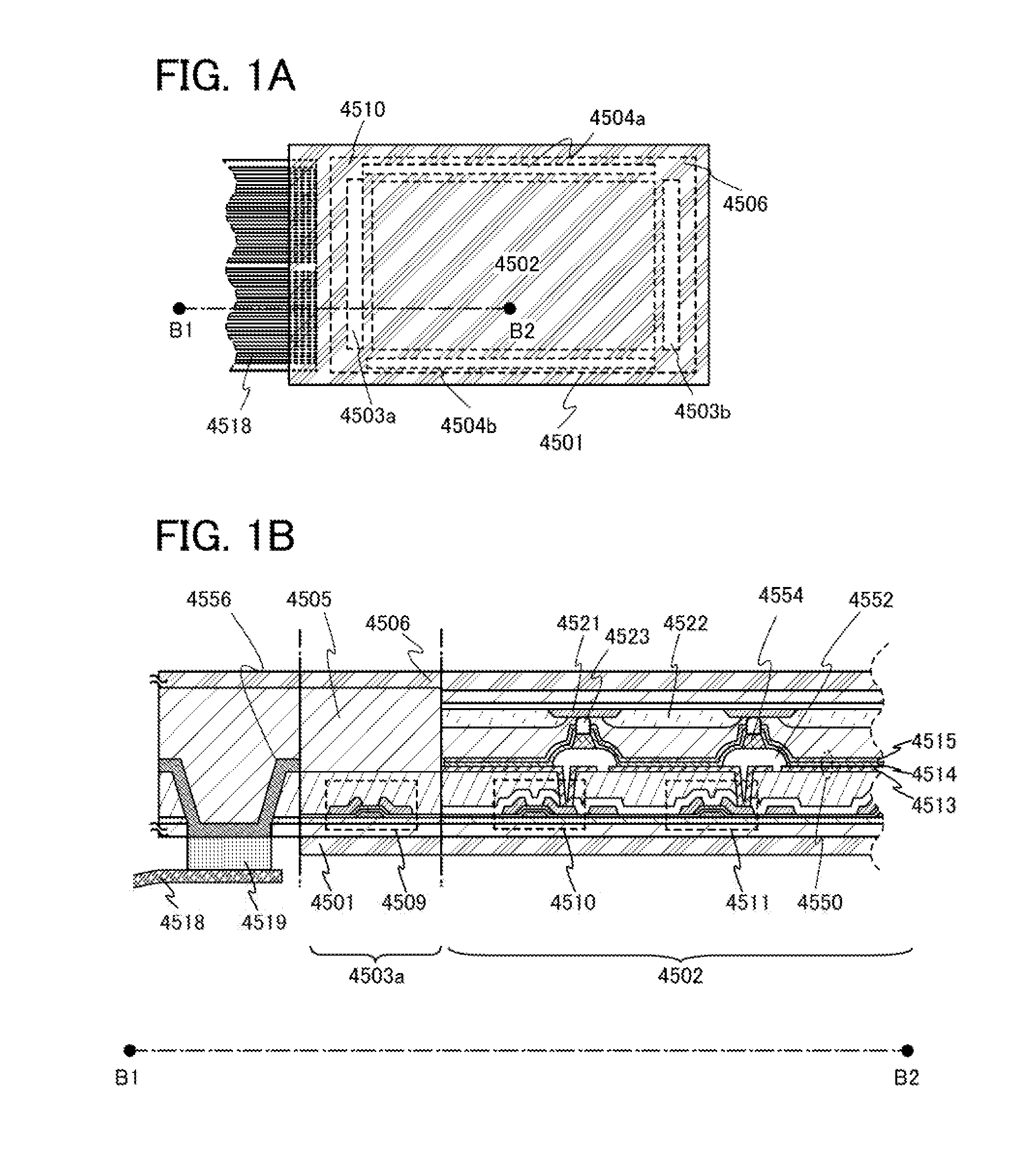
[0044]Next, an example of an active matrix Light-emitting device is described with reference to FIGS. 1A and 1B. Note that FIG. 1A is a top view of a light-emitting device and FIG. 1B is a cross-sectional view taken along dashed line B1-B2 in FIG. 1A.

[0045]The light-emitting device shown in FIG. 1A is provided with a pixel portion 4502, signal line driver circuits 4503a and 4503b, and scan line driver circuits 4504a and 4504b which are provided over a first substrate 4501. In addition, a second substrate 4506 is provided over the pixel portion 4502, the signal line driver circuits 4503a and 4503b, and the scan line driver circuits 4504a and 4504b.

[0046]Note that the first substrate 4501 and the second substrate 4506 are formed using flexible substrates.

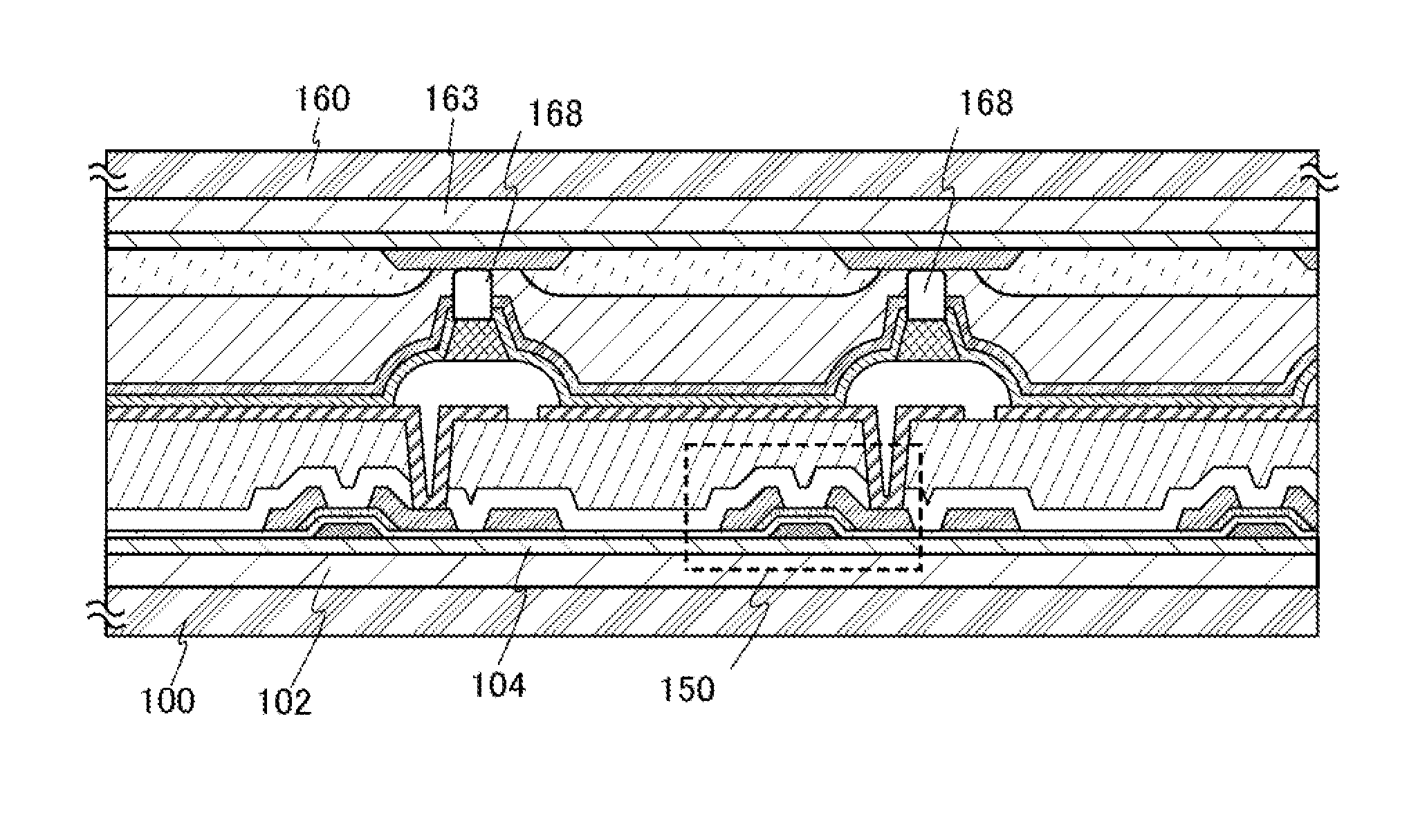
[0047]Further, in the light-emitting device shown in FIG. 1B, transistors 4509, 4510, and 4511 are formed over the first substrate 4501, and a light-emitting element 4550 is formed over the transistors 4510 and 4511.

[0048]Light from ...

embodiment 2

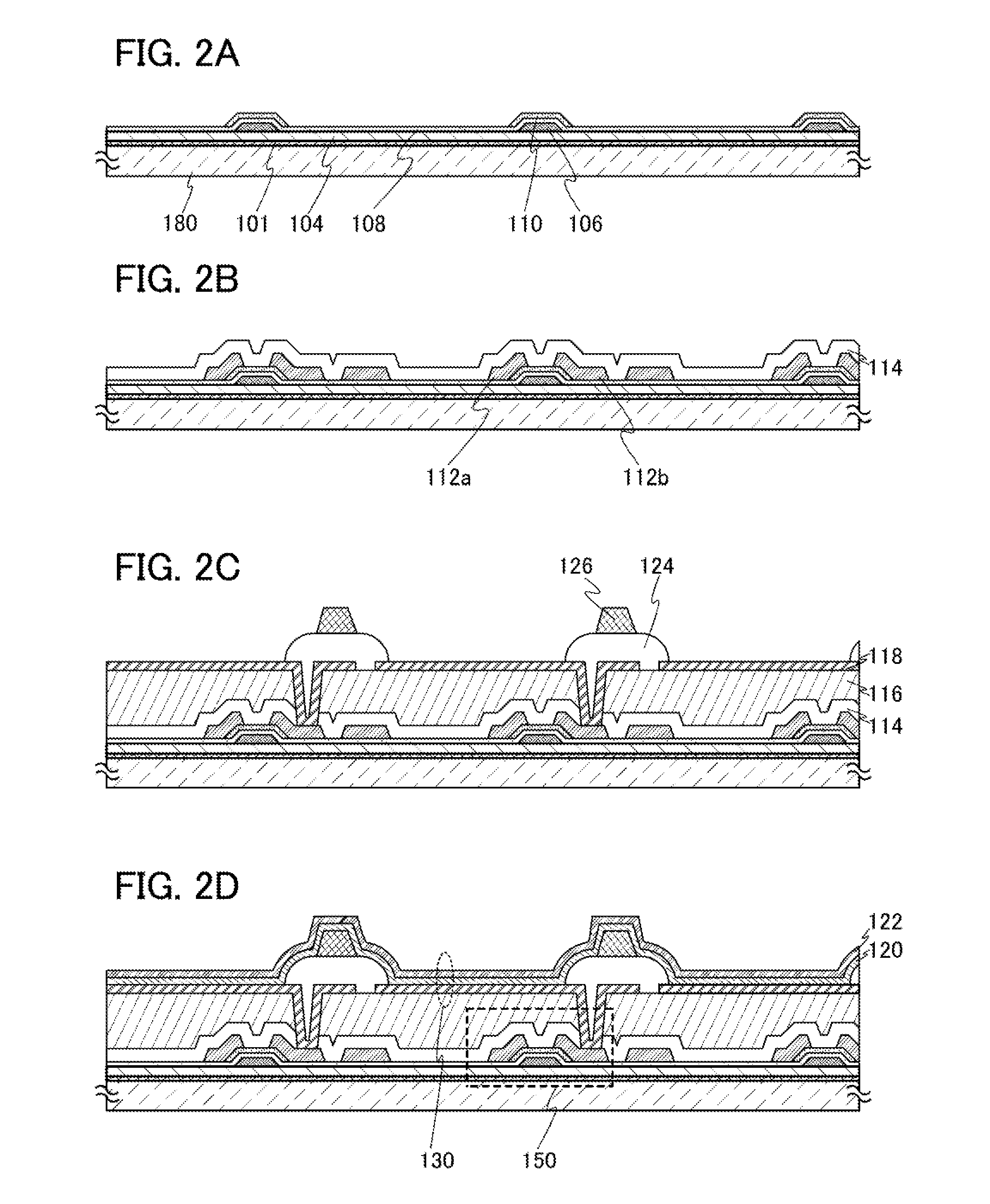
[0064]A method for manufacturing the light-emitting device illustrated in FIGS. 1A and 1B will be described with reference to FIGS. 2A to 2D, FIGS. 3A to 3C, FIGS. 4A and 4B, and FIGS. 5A and 5B.

[0065]First, a first separation layer 101 is formed over a third substrate 180, and a first buffer layer 104 is formed over the first separation layer 101. It is preferable that the first buffer layer 104 be formed successively so that the first separation layer 101 is not exposed to air. The successive formation prevents dust or impurities from entering a portion between the first separation layer 101 and the first buffer layer 104 (see FIG. 2A).

[0066]The third substrate 180 may be a glass substrate, a quartz substrate, a sapphire substrate, a ceramic substrate, a metal substrate, or the like. Alternatively, a plastic substrate which can withstand the processing temperature of this embodiment may be used. In the case where a plastic substrate is used, the separation layer 101 is not necessa...

embodiment 3

[0140]Structures of a spacer, a coloring layer, and a fixed portion which are used in the light-emitting device of this invention, which are different from those of the spacer 126, the coloring layer 166, and the fixed portion 168 which are described in Embodiment 2, are described with reference to FIGS. 6A to 6C.

[0141]Note that the same reference numerals are used for the same parts as those of the light-emitting device in Embodiment 1, and description of the parts with the same reference numerals will be omitted here.

[0142]A light-emitting device in FIG. 6A is an example in which a spacer 208 is bonded to the first bonding layer 170 by welding and also bonded to the partition 124 by welding by laser light irradiation. A material which absorbs visible light is added to the spacer 208, and the spacer 208 is firmly fixed to the first bonding layer 170 and the partition 124. Further, the light-emitting layer 120 formed on the top surface and part of the side surface is separated by th...


PUM


Abstract

An object is to provide a method for manufacturing a light-emitting device including a flexible substrate, in which separation is performed without separation at the interface between the light-emitting layer and the electrode. A spacer formed of a light absorbing material which absorbs laser light is formed over a partition of one of substrates, a coloring layer is formed over the other substrate, and the substrates are bonded to each other with the use of a bonding layer. The light-emitting layer and the electrode which are formed over the spacer are irradiated with laser light through the coloring layer, so that at least the bonding layer among the light-emitting layer, the electrode, the coloring layer, and the bonding layer is melted to form a fixed portion where the bonding layer and the spacer are bonded by welding.

Description

BACKGROUND OF THE INVENTION[0001]1. Field of the Invention[0002]One embodiment of the present invention relates to a light-emitting device utilizing electroluminescence. Further, an embodiment of the present invention relates to an electronic device using the light-emitting device.[0003]2. Description of the Related Art[0004]In recent years, research and development have been extensively conducted on light-emitting elements including electroluminescence (EL). In a basic structure of such a light-emitting element, a layer including a light-emitting substance is provided between a pair of electrodes. By voltage application to this element, light emission can be obtained from the light-emitting substance.[0005]Since the above light-emitting element is a self-luminous type, a light-emitting device using this light-emitting element has advantages such as high visibility, no necessity of a backlight, low power consumption, and the like. Further, such a light-emitting element also has adva...

Claims


Application Information

Patent Timeline
Patent Type & Authority Patents(United States)
IPC IPC(8): H01L21/00H01L33/00
CPCH01L27/3246H01L51/525H01L51/56H01L51/0024H01L51/003Y02E10/549Y02P70/50H10K59/122H10K71/50H10K71/80H10K50/8428H10K71/00H01L21/76841H01L23/145H10K77/111H10K50/865
Inventor HATANO, KAORUCHIDA, AKIHIROSHIMOMURA, AKIHISAYAMAZAKI, SHUNPEI
Owner SEMICON ENERGY LAB CO LTD
Why Eureka
Try Eureka