
Method and apparatus for improving dynamic range of a touchscreen controller

a touchscreen controller and dynamic range technology, applied in the field of touchscreen systems, can solve the problems of increasing the cost and size of components, reducing the gain and resolution of the measurement system, and the capacitance measured by the sensors, so as to improve the dynamic range of the touchscreen system, reduce the size of the system, and reduce the cost.

Active Publication Date: 2013-12-03
QUALCOMM INC
View PDF29 Cites 31 Cited by
  • Summary
  • Abstract
  • Description
  • Claims
  • Application Information

AI Technical Summary

Benefits of technology

The solution enhances the dynamic range of the touchscreen system by effectively canceling out unwanted capacitances, enabling accurate touch detection even under environmental changes without increasing component size or cost, thus improving resolution and reliability.

Problems solved by technology

One disadvantage of capacitance systems is that capacitance measured by the sensors will include not only the capacitance caused by a user touching the screen, but also the sensor capacitance of each sensor as well as other parasitic capacitances.
However, using large integrating capacitors undesireably increases cost and size of components, as well as reducing the gain and the resolution of the measurement system.
Another disadvantage of prior capacitance systems is that even if a large enough integration capacitor is chosen to compensate for the initial capacitance added by the sensor capacitance and the parasitic capacitances, these capacitances can change with environmental changes.
For example, with increased humidity the added moisture in the air typically increases these unwanted capacitances which can cause an integration cap that was previously large enough to no longer be able to handle the increased measured capacitance due to the environmental changes.
In such a case, the measurement system will no longer be able to tell when a sensor is being touched and the touchscreen system will become inoperable until the environment becomes less humid.

Method used


Image

  • Method and apparatus for improving dynamic range of a touchscreen controller
  • Method and apparatus for improving dynamic range of a touchscreen controller
  • Method and apparatus for improving dynamic range of a touchscreen controller

Examples


Embodiment Construction

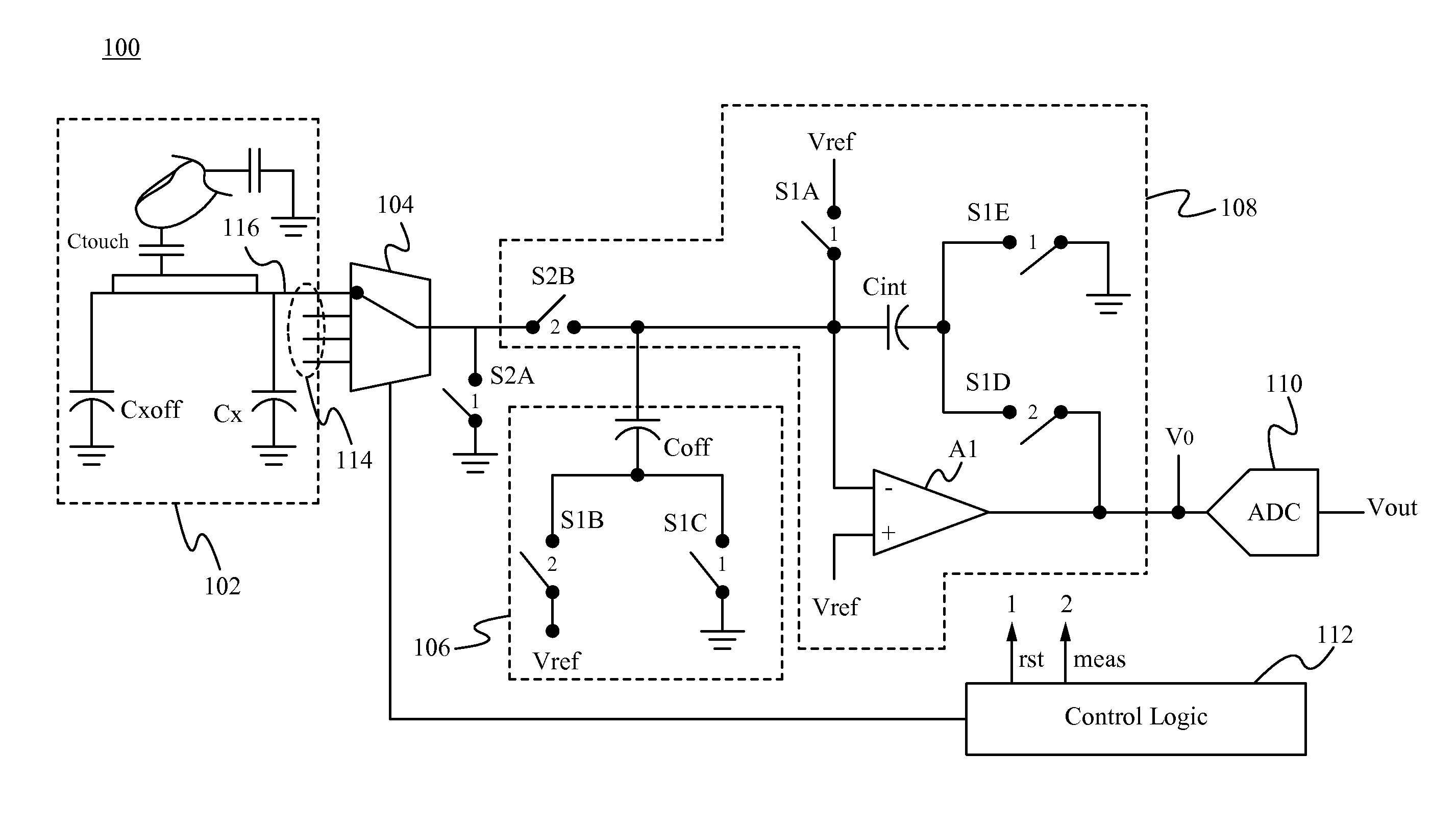
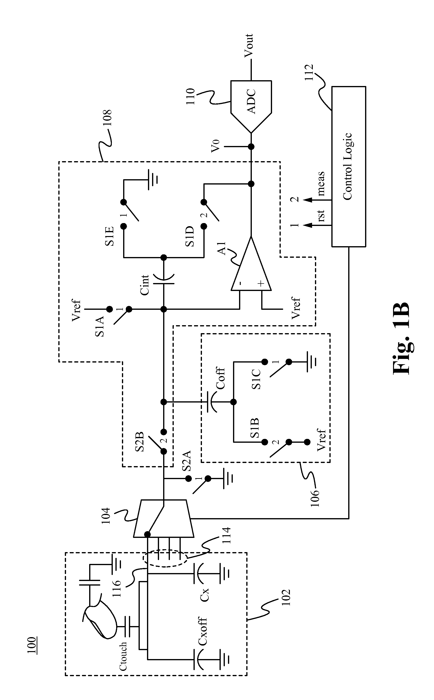
[0021]Embodiments of the present application are directed to a touchscreen capacitance-to-voltage converter circuit. Those of ordinary skill in the art will realize that the following detailed description of the touchscreen circuit is illustrative only and is not intended to be in any way limiting. Other embodiments of the touchscreen circuit will readily suggest themselves to such skilled persons having the benefit of this disclosure.

[0022]Reference will now be made in detail to implementations of the touchscreen circuit as illustrated in the accompanying drawings. The same reference indicators will be used throughout the drawings and the following detailed description to refer to the same or like parts. In the interest of clarity, not all of the routine features of the implementations described herein are shown and described. It will, of course, be appreciated that in the development of any such actual implementation, numerous implementation-specific decisions be made to achieve t...


PUM


Abstract

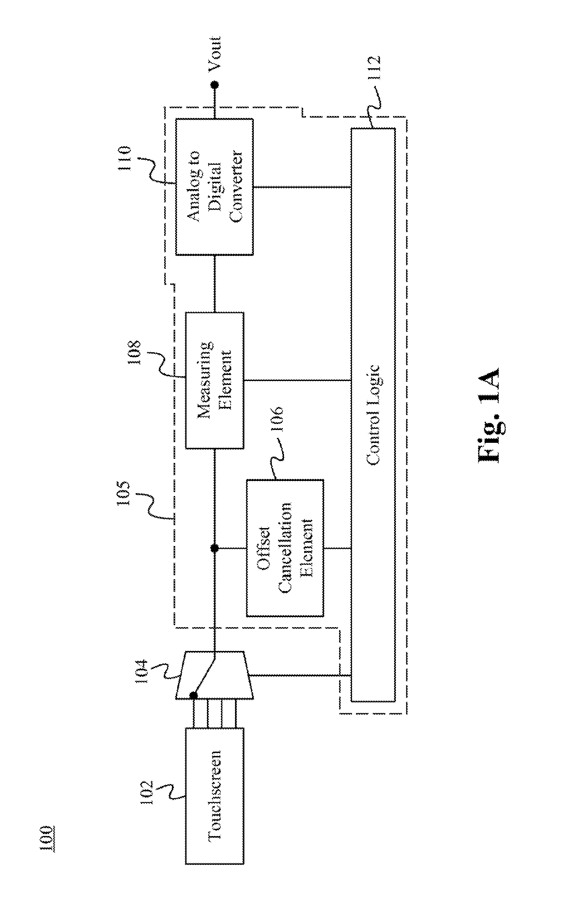
A touchscreen system for increasing the dynamic range of the system comprising a touchscreen coupled to an offset cancellation element and a capacitance measuring element. The offset cancellation element is configured to be dynamically changed in capacitance such that it offsets parasitic and sensor capacitances of the touchscreen sensors thereby leaving only touch event capacitance to be measured by the measuring element. The offset cancellation element is able to adjust to the initial unwanted capacitances of each sensor as well as dynamically adjust to changes in the unwanted capacitance due to the environment. In some embodiments, the offset cancellation element is a capacitance digital-to-analog converter that is controlled by a controller for offsetting the unwanted capacitance. As a result, the touchscreen system is able to utilize a small integrating capacitor thereby lowering cost and improving the dynamic range of the system.

Description

RELATED APPLICATIONS[0001]This application claims priority under 35 U.S.C. §119(e) of the U.S. provisional patent application Ser. No. 61 / 326,830, filed Apr. 22, 2010, and titled “Differential Capacitive Touchpad Circuit and Method,” which is hereby incorporated by reference in its entirety.[0002]The following co-owned, co-filed, and co-pending applications, U.S. patent application Ser. No. 12 / 986,841, titled “System for and Method of Transferring Charge to Convert Capacitance to Voltage for Touchscreen Controllers,” U.S. patent application Ser. No. 12 / 986,881, titled “Noise Cancellation Technique for Capacitive Touchscreen Controller Using Differential Sensing,” U.S. patent application Ser. No. 12 / 986,991, titled “System Integration of Tactile Feedback and Touchscreen Controller for Near-Zero Latency Haptics Playout,” U.S. patent application Ser. No. 12 / 987,008, titled “Use of Random Sampling Technique to Reduce Finger-Coupled Noise,” and U.S. patent application Ser. No. 12 / 986,905...

Claims


Application Information

Patent Timeline
Patent Type & Authority Patents(United States)
IPC IPC(8): G06F3/045
CPCG06F3/0418G06F3/044H03K17/96H03K2217/96062H03K17/9622
Inventor JOHARAPURKAR, ASHUTOSH RAVINDRACHAN, PATRICK
Owner QUALCOMM INC
Learn More