Method and a device for stabilizing aiming direction for rifles and handguns and fire arm

a technology for stabilizing aiming direction and rifles, which is applied in the direction of aiming means, butts, weapons, etc., can solve the problems of limited accuracy of fire in rifle shooting and handgun shooting, lack of weapon precision or quality, and quality of weapon and ammunition, etc., to achieve fast changes, easy to aim, and long time to choose

Active Publication Date: 2013-12-10
ANDERSSON
View PDF8 Cites 19 Cited by
  • Summary
  • Abstract
  • Description
  • Claims
  • Application Information

AI Technical Summary

Benefits of technology

[0014]The present invention regards a method and a device designed in such a way that movements of the barrel at aiming are attenuated by means of a servo system stabilizing the orientation of the barrel built-in in the weapon. In the servo system measuring means are included continuously measuring the rotation speed vertically and horizontally of the barrel and motors able to change the direction of the barrel in relation to the butt end so that the orientation of the barrel is stabilized whereby the aiming of the weapon in the desired direction is simplified and the accuracy of fire increases. By means of the stabilization the unintentional barrel movements, appearing at the aiming when the marksman, without having any physical support for the weapon, tries to control the sight direction towards the target, are counteracted. The technique may be applied for all kinds of rifles and also for handguns, like pistols and revolvers.
[0016]The invention comprises a rifle or a small arm designed in such a way that the shot at aiming is supported by a stabilizing servo system which attenuates the fast and unintentional barrel movements, whereby the marksman more easily can control the aiming direction towards a desired hit position and, by the calmer movement of the barrel and aiming direction also get a longer time to choose the right firing moment.
[0017]In a rifle or a handgun designed according to the invention the weapon is divided into two mutually movable parts, a front part, in which the barrel is included, and the butt end. The two parts are movable in relation to each other in a common point where they are connected by a biaxial bearing a hinge, which provides movability horizontally and vertically. The bearing is placed where the butt end adjoins the front part. The angle between the orientation of the butt end and the barrel is regulated by a servo system controlling the angle between the butt end and the barrel so that fast changes in the barrel orientation are counteracted and attenuated, which makes it easier to aim and to fire a shot in a desired direction. The turning torque changing the barrel orientation is accomplished by applying a turning torque in the opposite direction by the servo system. If eg the barrel shall be turned clockwise in order to compensate an externally, i.e. by the marksman, imposed movement, the butt end is turned anticlockwise. The moment of inertia of the butt end causes a turning torque to act on the barrel the direction of which is then changed. If the butt end at the rear end rests against a more or less solid object, in rifle shooting normally the shoulder of the marksman, the turning torque increases. In the case of shooting with handguns the conditions are principally similar but the shorter butt end and the fact that the weapon does not have contact with any big mass at the rear end, as is the case in rifle shooting (the shoulder of the marksman), means that the moment of inertia of the butt end becomes of greater importance. In the embodiment shown as an example is shown how the mass of the butt end may be arranged so that the heavier objects are placed farther away from and behind the bearing in order to give the butt end a moment of inertia great enough. In addition attenuating unintentional fast movements of the barrel the stabilizing servo system acts so that the movement of the barrel upwards, which arises at the recoil after a shot is also attenuated, so that one, with a weapon designed according the present patent and especially a semiautomatic rifle, is able to fire a well directed second shot faster.

Problems solved by technology

The accuracy of fire in rifle shooting and in handgun shooting is limited inter alia of the quality of the weapon and ammunition and of the kind of the sights used.
For modern weapons, however, the spread caused by shortcomings of the weapon precision or the quality of the ammunition by free hand shooting, i.e. without any external support for the weapon, is small compared to the spread caused by the marksman himself by not being able to hold the weapon still enough during the aiming and for this reason will have it difficult to make a firing in the direction desired.
What, inter alia, characterizes the unintentional barrel movements during the aiming is that these movements are comparatively fast and relatively small compared to the intentional changes of the aiming direction, which are bigger and slower.
The pipe around the barrel increases the total weight and moves the point of gravity forward which is a drawback since more power is then needed to hold the rifle horizontally.
A drawback with the design according to the U.S. Pat. No. 5,834,677 is that the sight, to be able to show the actual direction of shot, must be mounted on the barrel surrounded by the pipe.
This complicates the design.
The weight and the positioning of these motors move the point of gravity forward and makes the weapon heavy in the front.
The method may imply a risk that the marksman by mistake fires a shot instead of activating the servo system.
Another drawback with this method of activating the servo system is that it reasonably needs considerable training to be applicable in an efficient and safe way.

Method used


Image

  • Method and a device for stabilizing aiming direction for rifles and handguns and fire arm
  • Method and a device for stabilizing aiming direction for rifles and handguns and fire arm
  • Method and a device for stabilizing aiming direction for rifles and handguns and fire arm

Examples


Embodiment Construction

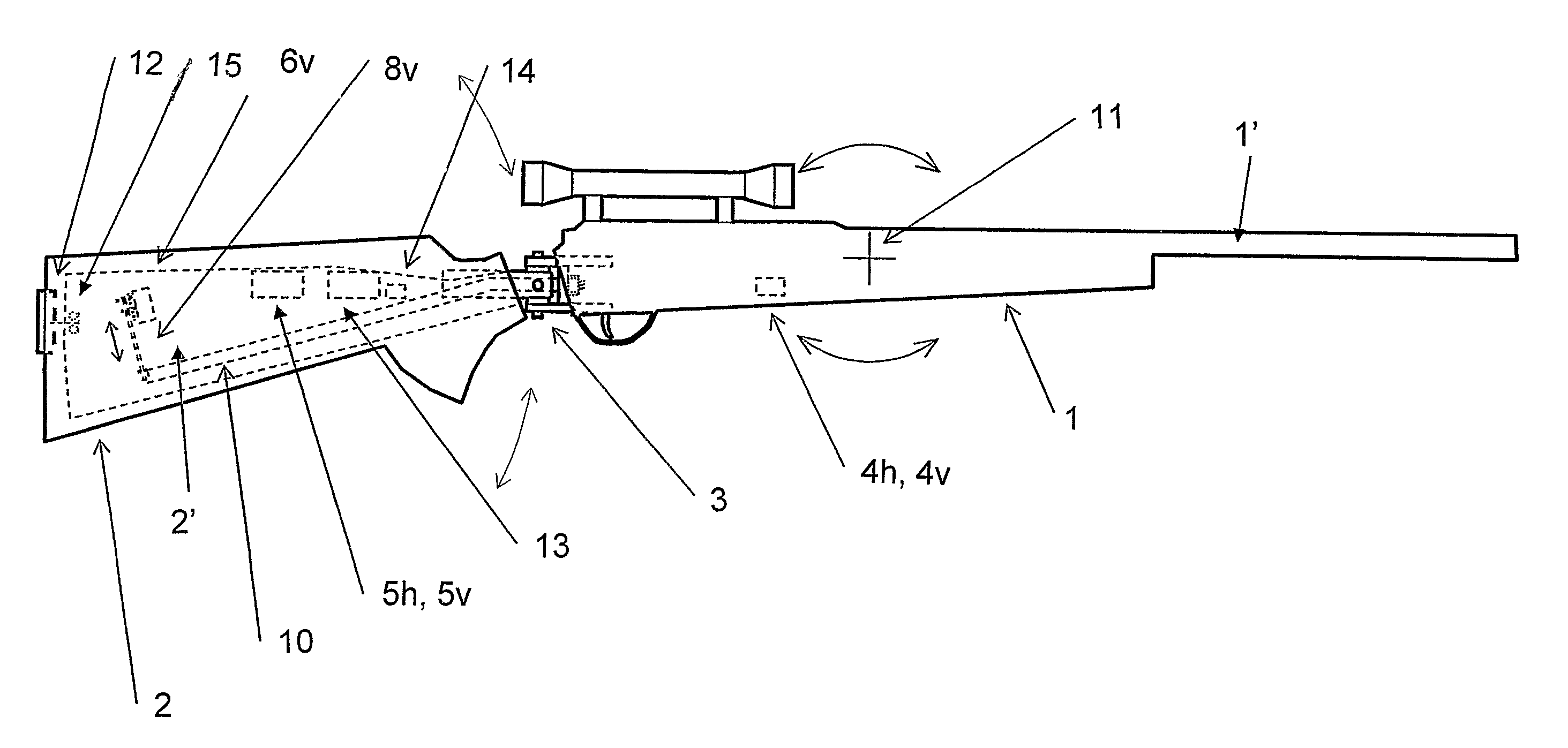
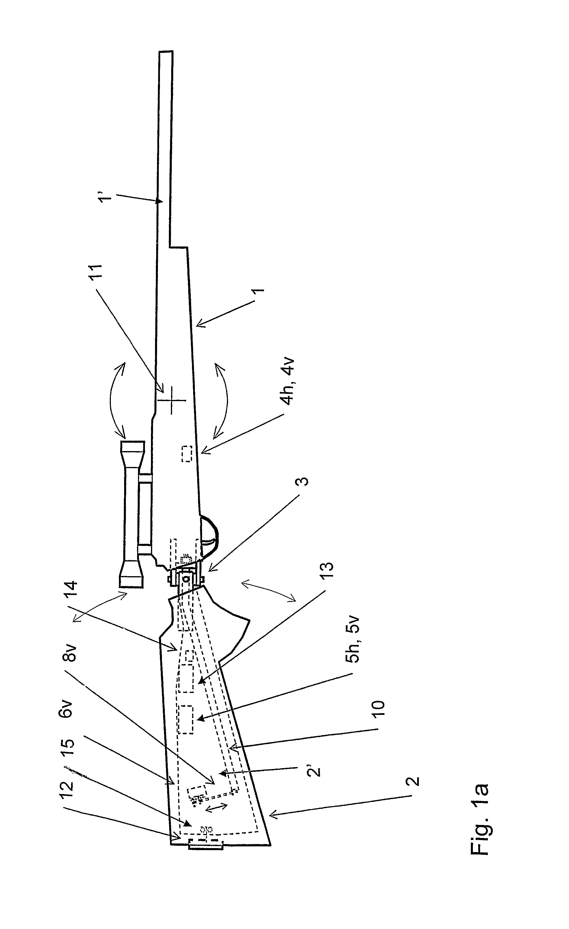
[0026]FIG. 1a The figure shows a rifle with a stabilized aiming direction seen from the right side. Certain important functional elements, which are hidden, are shown in broken lines. Certain hidden elements are not shown in the drawing. Between the two mutually movable parts, front part 1 and the butt end 2, parts of a hinge 3, a bearing 3, which gives the two parts movability horizontally and vertically may be seen. The gap between the butt end and the front part have for clarity reasons been made bigger than what is needed to give the desired movability. Through the bearing 3 the rod 10 applied in the front part protrudes backwards in the butt end. At the end of the rod the arm 8v is coupled so that it can transmit a rotational movement of the motor 6v to a mainly linear and vertical movement of the rod 10 end, whereby the angle between the butt end and the barrel can be changed. Parts which give movement horizontally have been deleted in the figure to increase the clarity. In th...


PUM


Abstract

A method for stabilizing a weapon, eg a rifle or a handgun, barrel movements when aiming by attenuating the influence of, primarily, unintentional barrel movements on the barrel orientation. The method is especially characterized in the steps ofproviding a hinge (3) between the barrel front part (1), which comprises the barrel (1′), and the weapon rear part (2), which comprises the weapon butt end (2′), for mutual movability between said parts;continuously detecting the barrel longitudinal direction movement in at least two planes; andcontrolling at least one angle between the butt end and the barrel longitudinal direction orientation, respectively, by means of a control system (4h, 4v, 5h, 5v, 6h,6v) so that changes in the barrel orientation are counteracted.The invention also relates to a device and a fire arm.

Description

BACKGROUND[0001]1. Technical Field[0002]Embodiments of the present invention relate to a method according to the introductory portion of the attached claim 1.[0003]Embodiments of the invention also relate to a device according to the introductory portion of the attached claim 18.[0004]Embodiments of the present invention further relate to a firearm according to claim 35.[0005]2. Prior Art[0006]Technique of the above referenced kind is previously known.[0007]The accuracy of fire in rifle shooting and in handgun shooting is limited inter alia of the quality of the weapon and ammunition and of the kind of the sights used. One reason for the point of impact to vary from shot to shot may eg be that the bullet weight and gun-powder load varies from cartridge to cartridge. Even if the weapon is fired in the same direction and under the same further conditions during a series of shots, the point of impact of the shots will get a certain spread which is caused by the quality of the materials...

Claims


Application Information

Patent Timeline
Patent Type & Authority Patents(United States)
IPC IPC(8): F41C23/14
CPCF41C23/12F41G3/12F41C23/20F41C27/22F41G1/46F41A27/30
Inventor ANDERSSON
Owner ANDERSSON
Why Eureka
Try Eureka