Muffler system with protector for small-sized vehicle

a technology for mufflers and protectors, which is applied in the direction of instruments, machines/engines, heat measurement, etc., can solve the problems of excessive bulging of muffler protectors, affecting the appearance, and the effect of curbing a rise in the temperature of muffler protectors needs to be enhanced further, so as to achieve efficient cooling, enhance external appearance, and reduce the effect of siz

Active Publication Date: 2013-12-10
HONDA MOTOR CO LTD
View PDF12 Cites 17 Cited by
  • Summary
  • Abstract
  • Description
  • Claims
  • Application Information

AI Technical Summary

Benefits of technology

[0006]The present invention has been made with the foregoing situation taken into consideration. An object of the present invention is to provide a novel muffler system with a protector for a small-sized vehicle, which is capable of solving the foregoing problems. In certain embodiments of the invention, by use of plate-shaped protector stays for supporting a muffler protector while covering an upper surface of a high-temperature portion of a muffler, hot air between the muffler and the muffler protector, which are arranged in such a manner as to be inclined upward from front to back, is actively discharged to the rear of a vehicle through heat convection. A rise in the temperature of the muffler protector is curbed and the muffler protector's intrinsic function of heat insulation is enhanced accordingly. By placing the muffler protector adjacent to the protector stays, the outward bulge of the muffler protector is curbed and external appearance is thus suitably arranged.

Problems solved by technology

The muffler with the protector disclosed in Patent Document 1, however, not only poses a problem that because the muffler protector bulges out around the muffler to a large extent, the muffler protector bulges out excessively and spoils the appearance in a case where, for example, the muffler protector is applied to a muffler placed near a seat for a rider.
This configuration also poses a problem that because hot air from the muffler directly reaches the muffler protector, the effect of curbing a rise in the temperature of the muffler protector needs to be enhanced further.

Method used


Image

  • Muffler system with protector for small-sized vehicle
  • Muffler system with protector for small-sized vehicle
  • Muffler system with protector for small-sized vehicle

Examples


Embodiment Construction

[0029]Embodiments of the present invention will specifically be described below on the basis of the accompanying drawings.

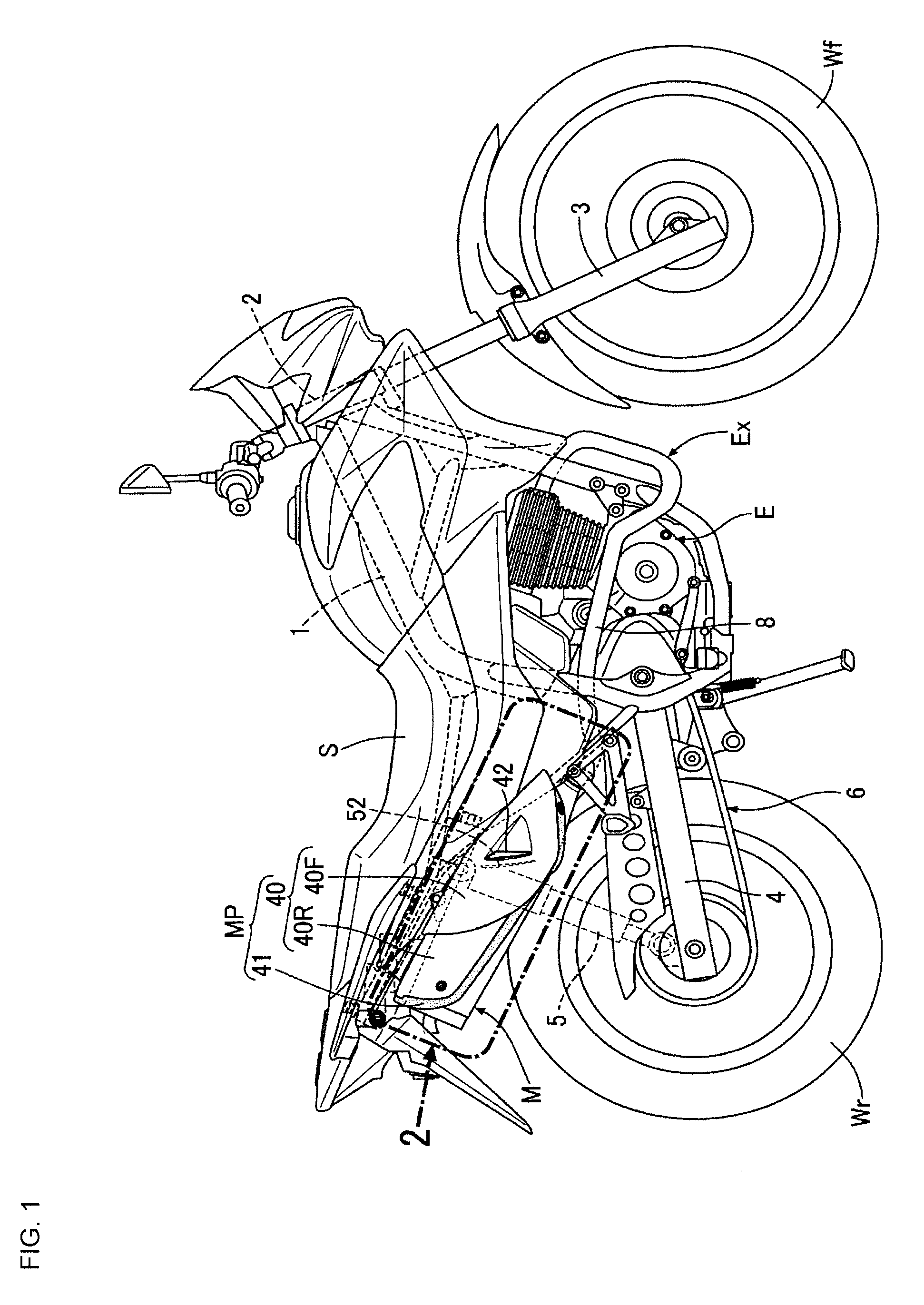
[0030]Front, rear, left, right, upper, and lower remarks in the descriptions of the following embodiment are based on a traveling direction of a motorcycle on which an exhaust system Ex is mounted.

[0031]An embodiment represents a case where a muffler system with a protector of the present invention is carried out as the exhaust system Ex which is mounted on the motorcycle.

[0032]FIG. 1 shows a saddle riding-type motorcycle including the muffler system with a protector according to an embodiment of the present invention. A head pipe 2 is provided at a front-end portion of a vehicle body frame 1 formed of pipe members and the like. A front wheel Wf is suspended on front forks 3 which are steerably supported by this head pipe 2. A swingarm 4, on which a rear wheel Wr is suspended, is mounted on a pivot in the rear portion of the vehicle body frame 1 in a vertically s...


PUM


Abstract

A muffler system can include an exhaust pipe configured to be connected to an exhaust port of an engine, and a muffler containing a catalyst. The muffler is configured to be connected to a downstream side of the exhaust pipe, and can include a first protector stay covering an upper surface of a high-temperature portion of the muffler. The first protector stay creates a front opening and a rear opening between an upper surface of the muffler and front and rear portions of the protector stay. A muffler protector is attached to the protector stay, the muffler protector being configured to cover an upper surface of the muffler.

Description

BACKGROUND[0001]1. Field[0002]The present invention relates to a muffler system with a protector which is connected to an exhaust system of an engine of a small-sized vehicle such as a motorcycle. Particularly, the present invention relates to a muffler system with a protector for a small-sized vehicle, in which a rise in the temperature of a muffler protector covering a muffler containing a catalyst is curbed, and a bulge of the muffler protector to the periphery of the muffler is curbed to enhance external appearance.[0003]2. Description of Related Art[0004]A muffler system with a protector for a motorcycle in which a muffler protector covering a muffler containing a catalyst is formed in a dual structure and the temperature of the surface of the muffler protector is thus lowered, for example, in Patent Document 1 (Japanese Patent No. 4400823).[0005]The muffler with the protector disclosed in Patent Document 1, however, not only poses a problem that because the muffler protector b...

Claims


Application Information

Patent Timeline
Patent Type & Authority Patents(United States)
IPC IPC(8): F01N13/08
CPCF01N13/14F01N1/083F01N2590/04F01N1/08F01N13/20
Inventor HAYAMA, YOSHITAKAYANAGISAWA, TAKAHIROYOKOYAMA, YASUHIROSHIBATA, HIROMI
Owner HONDA MOTOR CO LTD
Why Eureka
Try Eureka