Methods of vehicle suspension

a technology of vehicle suspension and suspension arms, which is applied in the direction of resilient suspensions, pivoted suspension arms, motorcycles, etc., can solve the problems of user physical illness at the least, crash through poor control of the vehicle, and fall apar

Inactive Publication Date: 2013-12-10
SWIST JASON
View PDF2 Cites 6 Cited by
  • Summary
  • Abstract
  • Description
  • Claims
  • Application Information

AI Technical Summary

Benefits of technology

[0008]It is an object of the present invention to mitigate disadvantages of prior art solutions to suspension systems for vehicles and more particularly to rear suspensions for motorcycles and front suspensions for automobiles.

Problems solved by technology

If the vehicle only had springs forming the suspension then whilst vertical motion would be absorbed the vehicle would “boat and wallow” or “rock and roll” along the road surface road making the user physically sick at the least or crashing through the poor control they had of the vehicle.
Either that or the incessant vibration would cause it to fall apart.
Firstly, they absorb any larger-than-average bumps in the road so that the upward velocity of the wheel over the bump isn't transmitted to the vehicle chassis.
Secondly, they keep the suspension at as full a travel as possible for the given road conditions so that the wheel is in contact with the road surface.

Method used


Image

  • Methods of vehicle suspension
  • Methods of vehicle suspension
  • Methods of vehicle suspension

Examples


Embodiment Construction

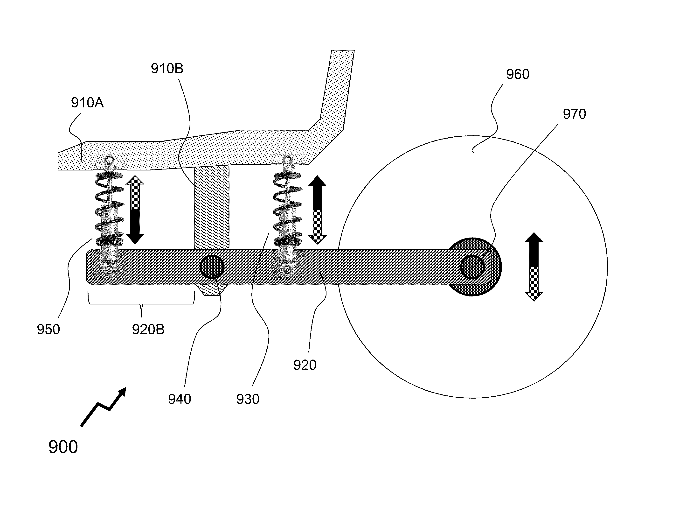
[0044]The present invention is directed to mitigating disadvantages of prior art solutions to suspension systems for vehicles and more particularly to rear suspensions for motorcycles and front suspensions for automobiles.

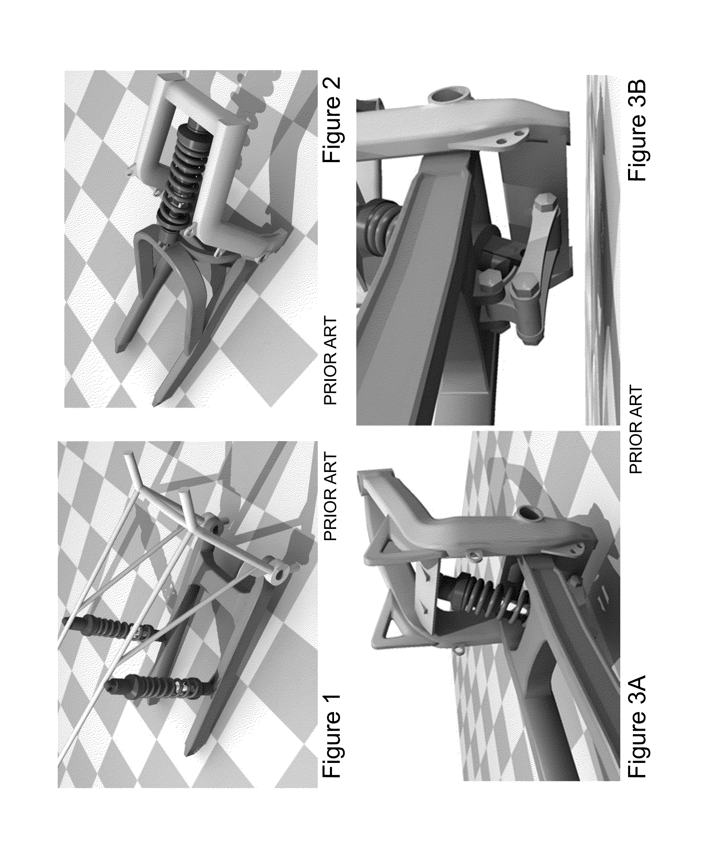
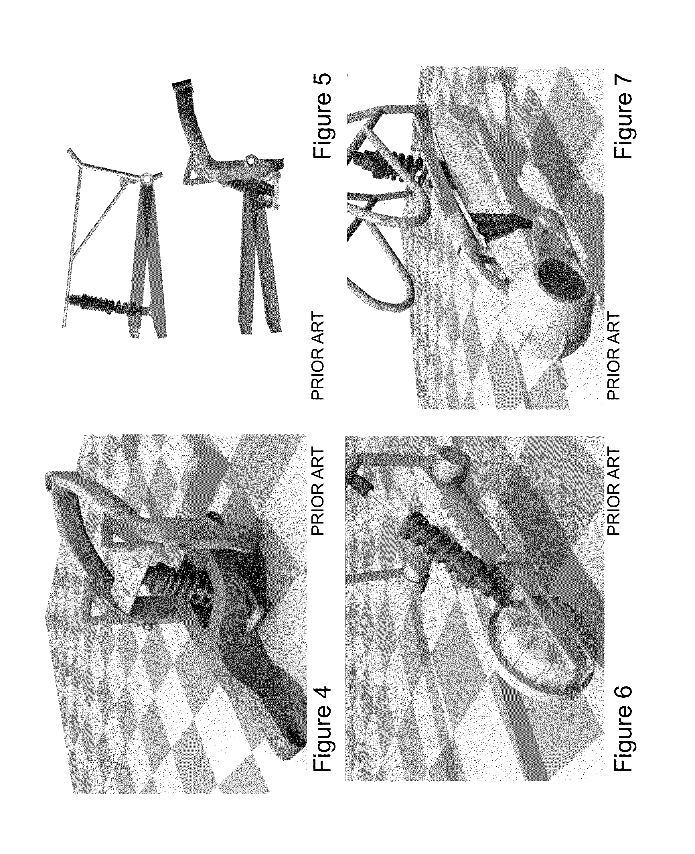
[0045]Considering firstly motorcycle suspension then the whilst front suspensions were almost universally adopted before 1914, rear suspensions were not and in fact some manufacturers did not use rear suspensions until after 1945. Amongst the earliest was the 1913 Indian Single with a swingarm suspended from a leaf spring and the 1913 Pope with wheels supported on a pair of plungers which were each suspended by a coil spring. Notable manufacturers of bikes with plunger suspension included Ariel, BMW, BSA, Indian, and Norton. However, these were gradually replaced by swingarms which evolved in many forms with time such that today motorcyclists unless interested in vintage motorcycles are unaware any other format existed.

[0046]The classic modern motorcycle suspension...


PUM


Abstract

Suspension systems must tradeoff multiple purposes including contributing to the vehicle's road holding / handling and braking for good active safety and driving pleasure as well as keeping vehicle's user(s) comfortable and reasonably well isolated from road noise, bumps, and vibrations, etc. Over the past 100 years many suspension systems have evolved but have in common the disposition of the hock absorber between the wheel and the fulcrum point of the wheel mounting to the vehicle. It would be, however, be beneficial to provide a suspension exploiting a dual-shock system wherein the two shock absorbers are in opposite states so that even under absorption of the vertical shock from the road surface there was still applied additional force for road contact to be maintained. It can also be shown to be beneficial in single-shock systems to place the shock the opposite side of the fulcrum point of the suspension system, counter to previous prior art solutions.

Description

CROSS-REFERENCE TO RELATED APPLICATIONS[0001]This patent application claims the benefit of U.S. Provisional Patent Application 61 / 471,752 filed Apr. 5, 2011 entitled “Methods of Vehicle Suspension.”FIELD OF THE INVENTION[0002]This invention relates to suspension systems for vehicles and more particularly to rear suspensions for motorcycles and front suspensions for automobiles.BACKGROUND OF THE INVENTION[0003]Suspension is the name given to the system of springs, shock absorbers and linkages that connects a vehicle to its wheels. Suspension systems serve multiple purposes including contributing to the vehicle's road holding / handling and braking for good active safety and driving pleasure as well as keeping vehicle's user(s) comfortable and reasonably well isolated from road noise, bumps, and vibrations, etc. These goals are generally at odds with one another, so the tuning of suspensions involves finding the right compromise. It is important for the suspension to keep the road wheel...

Claims


Application Information

Patent Timeline
Patent Type & Authority Patents(United States)
IPC IPC(8): B60G3/18
CPCB60G3/06B62K25/26B62K25/283B60G3/14B60G2300/12
Inventor SWIST, JASON
Owner SWIST JASON
Why Eureka
Try Eureka