Vector control for an axial gap motor

a technology of axial gap and control, which is applied in the direction of magnetic circuit, field or armature current control, electric energy management, etc., can solve the problem of increasing the upper limit of the controllable range of the output torque of the motor, and achieve the effect of strengthening and weakening the magnetic flux generated by the permanent magnet of the rotor

Inactive Publication Date: 2013-12-10
HONDA MOTOR CO LTD
View PDF20 Cites 3 Cited by
  • Summary
  • Abstract
  • Description
  • Claims
  • Application Information

AI Technical Summary

Benefits of technology

[0007]The present invention has been accomplished in view of the aforementioned problems, and it is therefore an object of the present invention to provide a controller for an axial gap-type motor capable of being operated at higher revolutional velocity with higher output torque by increasing a controllable range thereof.

Problems solved by technology

Moreover, by supplying the field current for weakening the magnetic flux generated by the permanent magnet of the rotor to the armature windings of the second stator, an induced voltage between the terminals of the armature windings of the first stator, and consequently, increasing the upper limit of the controllable range of the output torque of the motor.

Method used


Image

  • Vector control for an axial gap motor
  • Vector control for an axial gap motor
  • Vector control for an axial gap motor

Examples


Embodiment Construction

[0032]Hereinafter, an embodiment of the present invention will be described in detail with reference to FIG. 1 to FIG. 6.

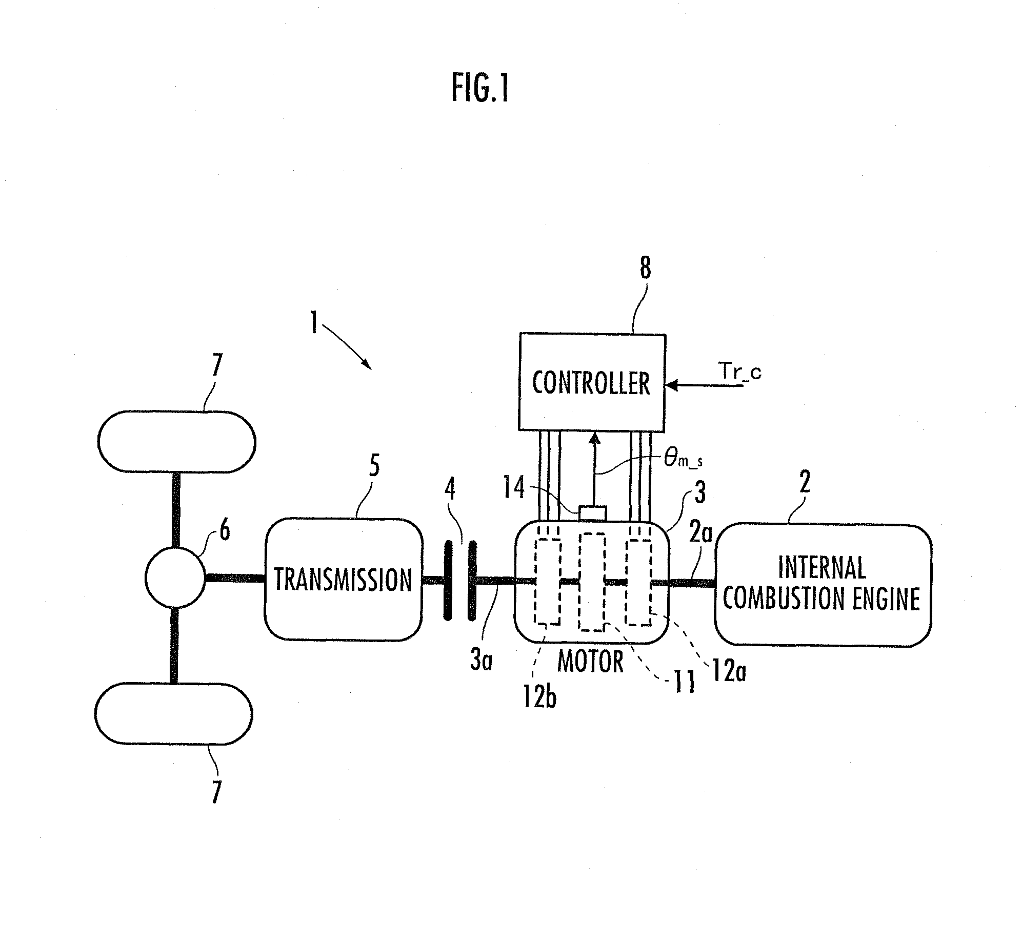
[0033]With reference to FIG. 1, an overall structure of a vehicle mounted with a motor of the present embodiment will be described. FIG. 1 illustrates the overall structure of the vehicle.

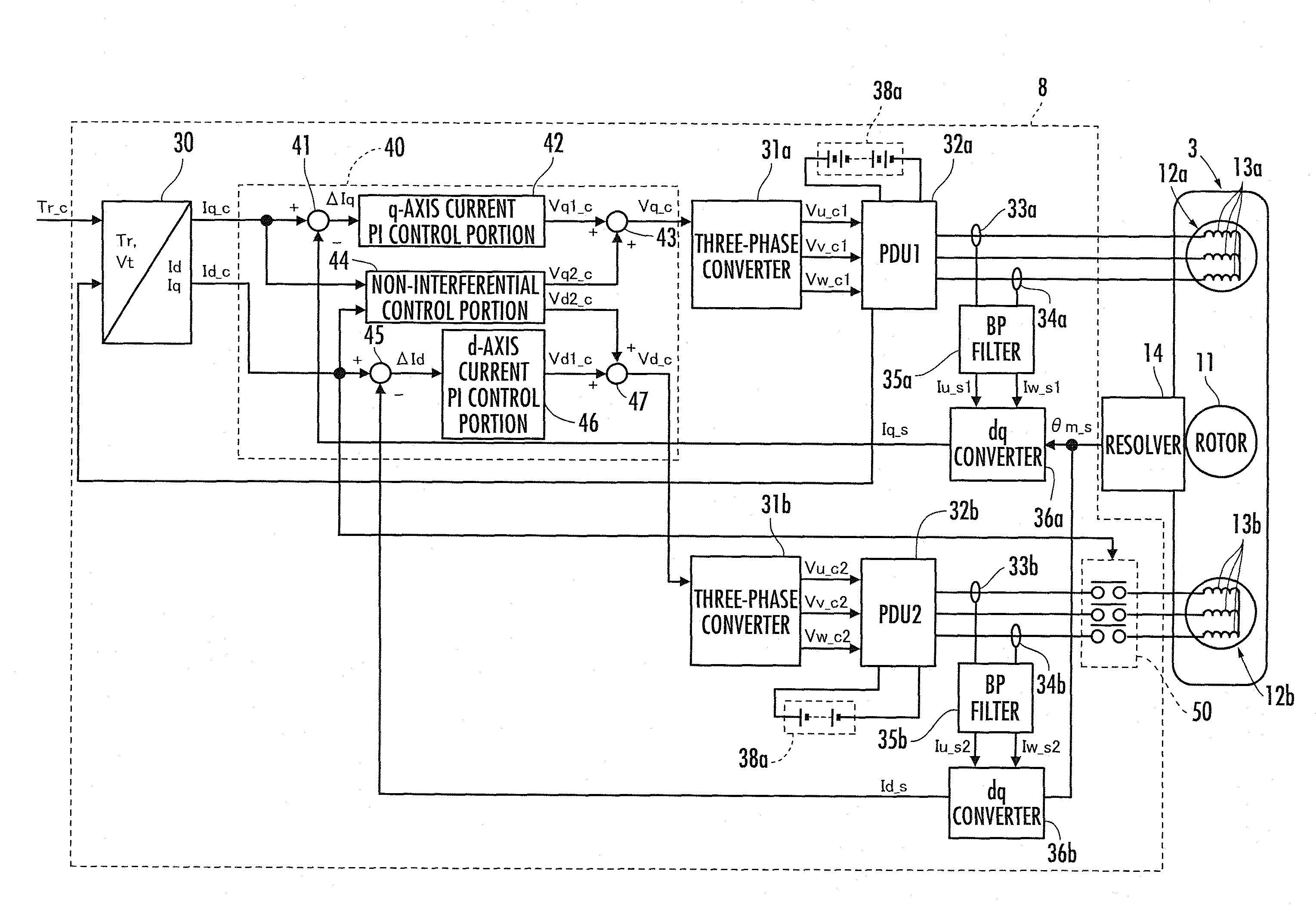
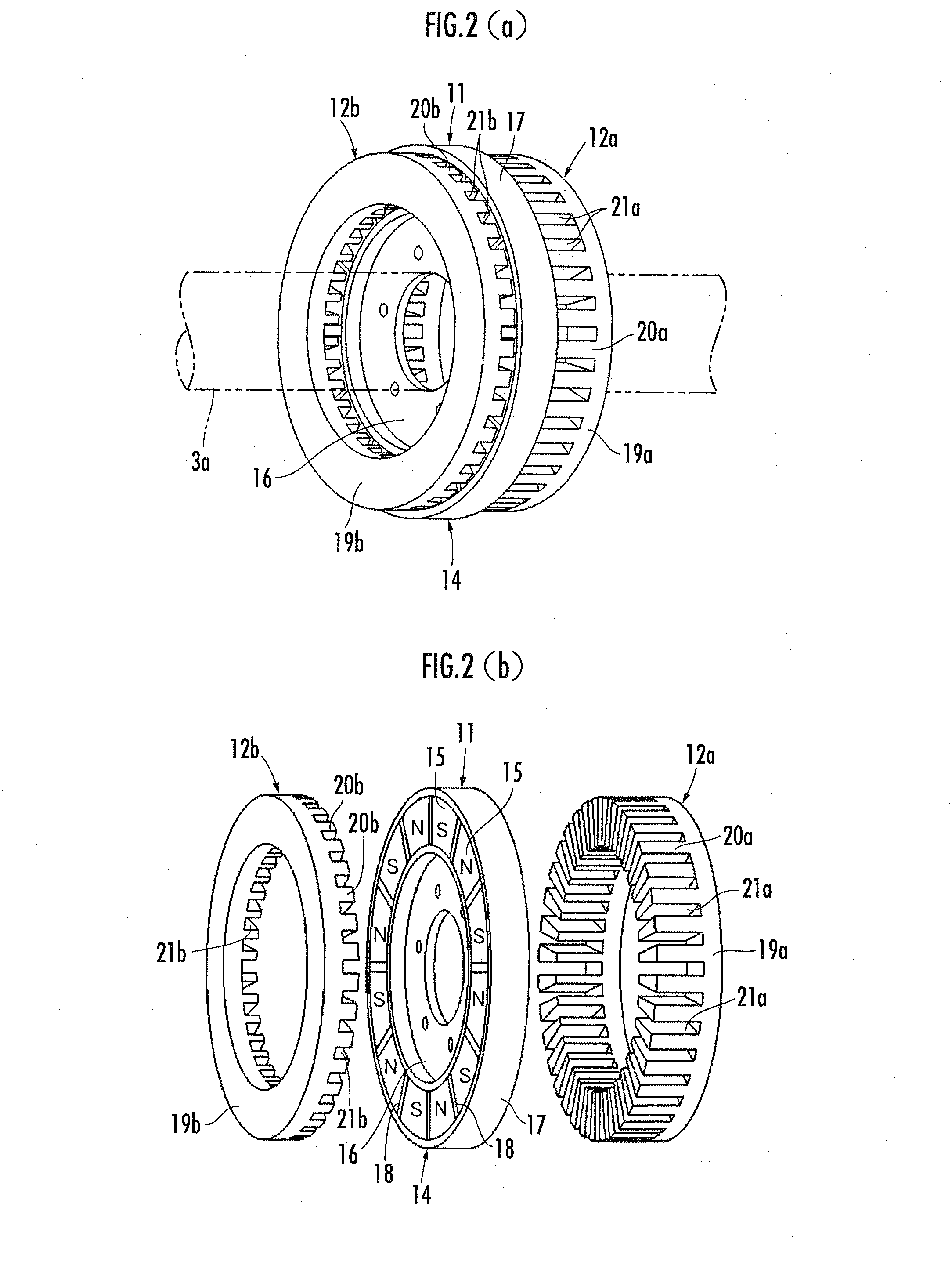
[0034]The vehicle 1 of the present embodiment is a hybrid vehicle of a parallel type and is provided with an internal combustion engine 2 serving as a main driving force generation source and a motor 3 serving as an auxiliary driving force generation source. The motor 3, to be described hereinafter, is an axial gap-type motor having a rotor 11, a first stator 12a and a second stator 12b. The motor 3 is provided with a resolver 14 serving as a revolution angle detection portion configured to detect a revolution angle of the rotor 11.

[0035]An output shaft 2a of the internal combustion engine 2 is coaxially and directly coupled with a revolution shaft 3a revolutionarily integrated w...


PUM


Abstract

A controller for an axial gap-type motor (3) comprises a rotor (11) having a permanent magnet and a first stator (12a) and a second stator (12b) opposed to each other with the rotor (11) interposed therebetween in the axial direction of revolution of the rotor (11). The controller further includes an electrification control portion which supplies a torque current (Iq) for generating a magnetic field to revolve the rotor (11) to an armature winding (13a) of the first stator (12a) and supplies a field current (+Id) for reinforcing the magnetic flux by the permanent magnet of the rotor (11) or a field current (−Id) for weakening the magnetic flux to an armature winding (13b) of the second stator (12b). Consequently, the controllable range of the motor is increased and the axial gap-type motor can be operated at higher velocity and higher torque.

Description

BACKGROUND OF THE INVENTION[0001]1. Field of the Invention[0002]The present invention relates to a controller for an axial gap-type motor.[0003]2. Description of the Related Art[0004]Conventionally, there has been known an axial gap-type motor provided with a rotor having a permanent magnet, two stators disposed at both sides of the rotor in an axial direction of revolution of the rotor, and an armature attached to each of the stators (for example, refer to Japanese Patent Laid-open No. H10-271784 and No. 2001-136721). According to the axial gap-type motor, it is possible to obtain a relatively high output torque although the rotor thereof is getting shorter in the axial direction.[0005]According to the conventional axial gap-type motor, the leak of a magnetic flux generated by an armature winding of the stator is reduced according to an electrification control by electrifying armature windings of both stators disposed at both sides of the rotor, and therefore, it is possible to inc...

Claims


Application Information

Patent Timeline
Patent Type & Authority Patents(United States)
IPC IPC(8): H02P1/00H02P3/00H02P7/06H02K21/24H02K16/04H02P6/06H02P6/08H02P6/15H02P6/28H02P21/00H02P21/06H02P21/10H02P21/12H02P21/22H02P25/026H02P27/04H02P27/08
CPCB60L15/025H02P21/00H02P21/0035H02P21/0089H02P21/06B60L7/14B60L11/14B60L15/007B60L15/2009Y02T10/70H02P2207/076Y02T10/641Y02T10/643B60L2240/12B60L2240/421B60L2240/423B60L2240/429B60L2240/441B60L2240/443Y02T10/7077Y02T10/7275H02K21/24Y02T10/72H02P21/22B60L50/16Y02T10/64Y02T10/7072
Inventor ATARASHI, HIROFUMI
Owner HONDA MOTOR CO LTD
Why Eureka
Try Eureka