Supercharge Your Innovation With Domain-Expert AI Agents!

RF coil assembly for use in magnetic resonance imaging

a magnetic resonance imaging and coil assembly technology, applied in the field of rf coil assembly for use in magnetic resonance imaging, can solve the problems of limited use of flexible coils in intra-operative applications, inability to remain in that shape, and difficulty in mechanical/geometrical adjustment of coils, etc., and achieve the effect of dramatic improvement of image quality

Active Publication Date: 2013-12-10
DEERFIELD IMAGING INC
View PDF11 Cites 4 Cited by
  • Summary
  • Abstract
  • Description
  • Claims
  • Application Information

AI Technical Summary

Benefits of technology

The present invention is a new coil construction that can be used in various MR applications such as the head, neck, and heart. It is flexible and user-friendly, without additional conformation devices. The arrangement allows for optimal positioning of the coil relative to the field of view, which can significantly improve image quality.

Problems solved by technology

That is the flexible coils typically can be bent into the required shape to match the anatomy, but have no ability to remain in that shape due to their elastic nature.
In this case, due to difficulty of cleaning or sterilizing the straps, the use of flexible coils in intra-operative applications is limited.
Coils, whether rigid or flexible, that are used for neurosurgical applications generally have rigid attachment to the patient table or directly to the patient, which makes the mechanical / geometrical adjustment of the coil difficult or impossible.
However they provide only a compromise in relation to the position of the coil antenna relative to the anatomy of the patient.
As rigid coils are necessarily sized to fit all, in many cases they do not properly fit the patient.
Also the mounting typically is restrictive as to the ability to properly orient the coil

Method used


Image

  • RF coil assembly for use in magnetic resonance imaging
  • RF coil assembly for use in magnetic resonance imaging
  • RF coil assembly for use in magnetic resonance imaging

Examples


Embodiment Construction

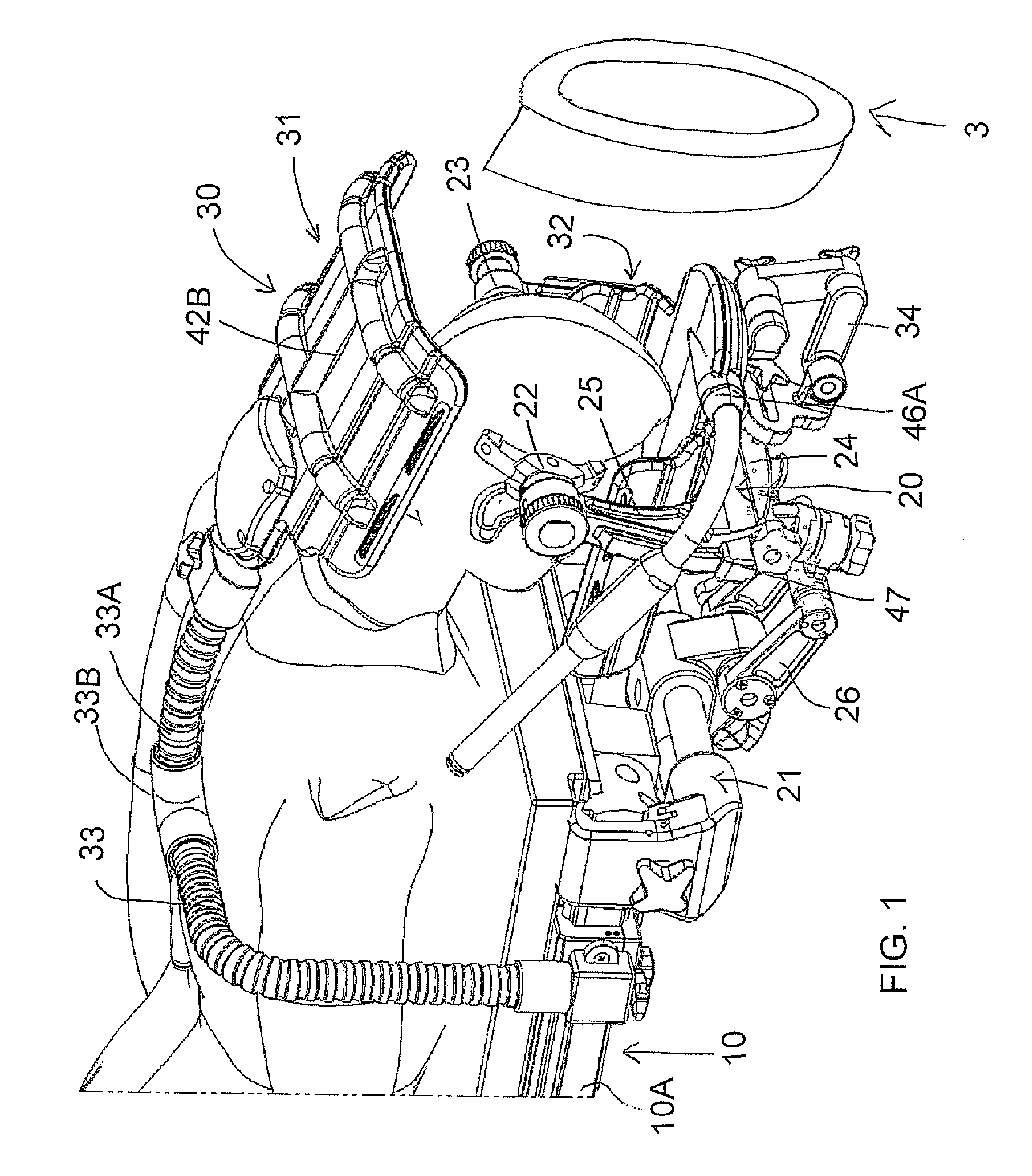
[0075]In FIG. 1 is shown an arrangement for carrying out Magnetic Resonance Imaging of a patient while the patient remains stationary on a patient support table. The arrangement provides a room in which is mounted a patient support table 10 with doors at one side of the room for entry into the room of a magnet 3 of an MR imaging system from a magnet bay. The table 10 described and illustrated herein is used in an arrangement where the patient remains in position on the table during surgery and while imaging is effected intra-operatively or post-operatively using MRI.

[0076]The MR is a high-field (e.g. 1.5 T or 3 T) magnet that moves on overhead rails between the two or more rooms as described above. The arrangement may be used in a typical three room configuration with the Angiography Room (AR) on the left, a Diagnostic Room (DR) in the middle, and an Operating Room on the right. The magnet moves on overhead rails between the rooms and can image in each.

[0077]The Patient Handling Sys...


PUM


Abstract

An apparatus for intra-operative MRI includes a patient table with a movable magnet and an RF coil having an upper portion and a lower portion. The upper portion is formed of a foam material flexible to different shapes with a pair of stiffeners formed of connected pivotal elements extending from a central back-bone embedded in the top sheet of the foam to hold the flexible material in the different shapes and is carried at one end of a flexible foam arm attached to a side rail of the table and stiffened by a longitudinal stiffener. A head clamp is attached to the table with a C-shaped holder for the skull clamp pins. The lower coil is movable by flexing about longitudinal lines to different curvatures and is held channel shaped by the C-shaped holder. It is attached at one longitudinal end to an adjustable mount connected to the head clamp.

Description

[0001]This invention relates to a RF coil assembly for use in magnetic resonance imaging. In particular aspects of the invention include a user adjustable semi-rigid flexible foam upper RF coil, a conformable support mechanism for the coil and a support for a lower coil.BACKGROUND OF THE INVENTION[0002]RF coils of various design are available for use in MR imaging. The coils are used to receive / transmit signal and in order to do this should be positioned directly on or immediately adjacent the human anatomy in an orientation so that the coil lies in a plane which is parallel to the axis of the bore of the magnet.[0003]The coils include a top portion and a bottom portion. In regard to coils for imaging the head, these are generally channel shaped and facing one another so as to envelope the head with side edges which are close or touching so that the head is surrounded by the two coil portions. Each coil portion includes an array of coil elements, typically four, so as to form a phas...

Claims


Application Information

Patent Timeline
Patent Type & Authority Patents(United States)
IPC IPC(8): G01V3/00
CPCG01R33/34007G01R33/34084G01R33/3415
Inventor SHVARTSBERG, ALEXANDERSCHELLEKENS, WAYNE THEODOREFALLAH-RAD, MEHRANTURENNE, CLAUDE
Owner DEERFIELD IMAGING INC
Features
  • R&D
  • Intellectual Property
  • Life Sciences
  • Materials
  • Tech Scout
  • Unparalleled Data Quality
  • Higher Quality Content
  • 60% Fewer Hallucinations
Learn More