
Multi-channel potentiostat for biosensor arrays

a potentiostat and biosensor technology, applied in the field of potentiostat circuits, can solve the problems of -term complications, personal health and economic costs, and the inability to maintain normoglycemia to manage diabetes

Inactive Publication Date: 2013-12-10
DARE MB INC
View PDF22 Cites 22 Cited by
  • Summary
  • Abstract
  • Description
  • Claims
  • Application Information

AI Technical Summary

Benefits of technology

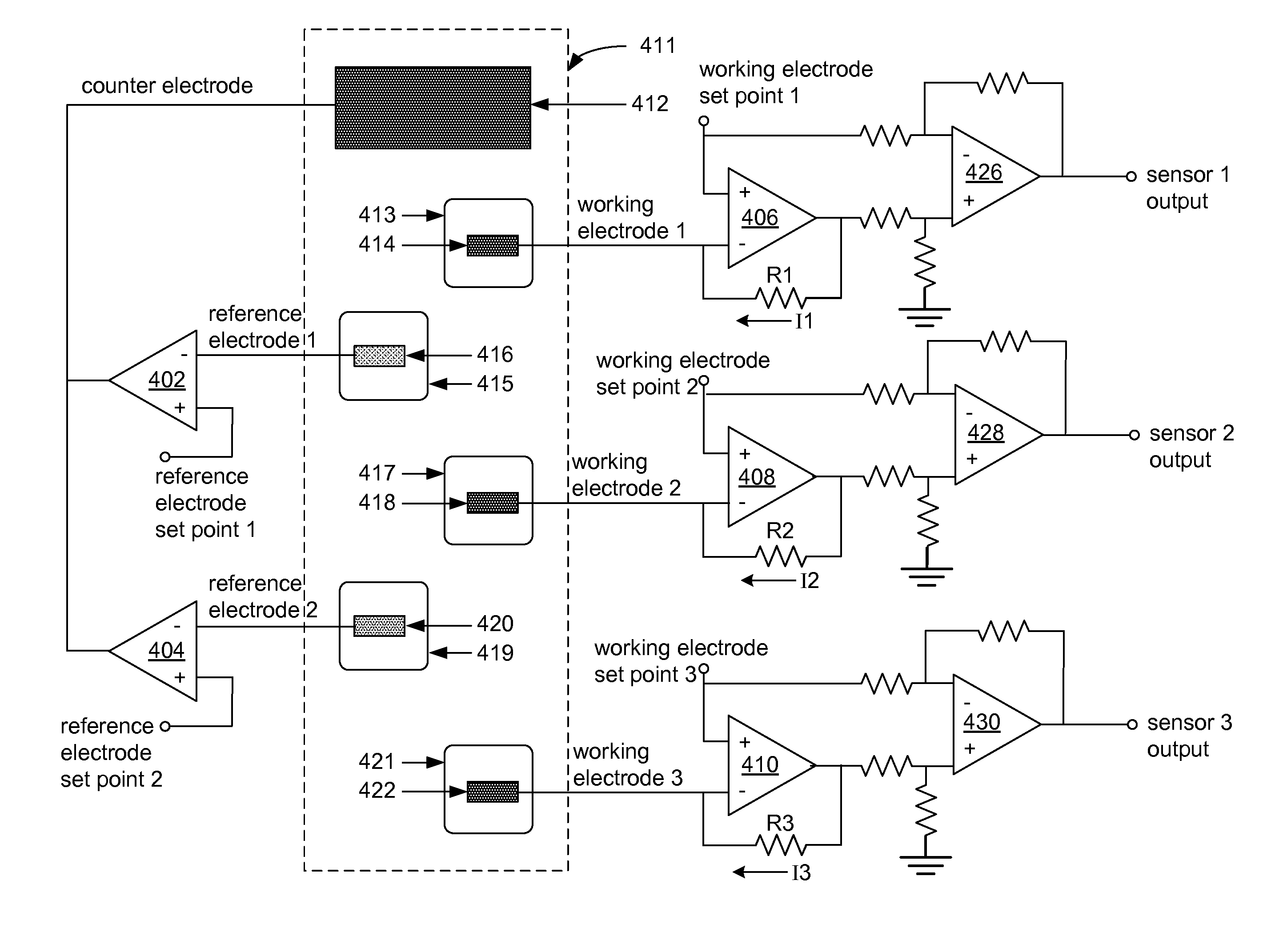
[0011]Improved potentiostat circuits for the control of biosensors (or alternatively, other chemical / electrochemical sensors) are provided. The potentiostat circuits and biosensors can be useful, for example, in medical applications, such as transdermal or implantable medical devices. According to an embodiment, a continuous monitoring device includes at least two working electrodes that are operative with a single control amplifier that is configured to provide a reference electrode and an counter electrode. Each of the respective working electrodes is utilized as part of a biosensor (or alternatively, an chemical / electrochemical sensor) for detecting or measuring an analyte, in vitro or in vivo. The operability of at least two working electrodes with a single control amplifier can advantageously allow for redundancy, sequential operation, and differential or ratiometric operation between available working electrodes, thereby allowing for continuous operation of the biosensors.

Problems solved by technology

For over five million Americans with insulin-dependent diabetes (IDDM) there are tremendous personal, health and economic costs associated with maintaining normoglycemia to manage diabetes.
The risks of poor glucose control include the life-threatening crises that can occur due to severe hypoglycemia, and the long-term complications that result from hyperglycemia.

Method used


Image

  • Multi-channel potentiostat for biosensor arrays
  • Multi-channel potentiostat for biosensor arrays
  • Multi-channel potentiostat for biosensor arrays

Examples


Embodiment Construction

[0023]Improved potentiostat circuits for the control of biosensors (or alternatively, other chemical / electrochemical sensors) are provided. The potentiostat circuits and biosensors can be useful, for example, in medical applications, such as transdermal or implantable medical devices. According to an embodiment, a biosensor includes at least two working electrodes that are operative with a single control amplifier that is configured to provide a reference electrode and a counter electrode. Each of the respective working electrodes is utilized as part of a biosensor (or alternatively, a chemical / electrochemical sensor) for detecting or measuring an analyte, in vitro or in vivo. The operability of at least two working electrodes with a single control amplifier can advantageously allow for redundancy, controlled switching between, differential or ratiometric operation between available working electrodes, thereby allowing for continuous operation of the biosensors.

[0024]The Internation...


PUM


Abstract

Arrays of biosensors are provided along with methods for operating the arrays of biosensors. The array of biosensors may include a first reference electrode that is connected to an input of a first control amplifier; a first working electrode and a second working electrode in proximity with the first reference electrode; and a counter electrode that is connected to at least an output of the first control amplifier, where the first control amplifier is operative with the counter electrode to maintain a first specified voltage between the first working electrode and the first reference electrode, and between the second working electrode and the first reference electrode. The array of biosensors optionally may further include a second reference electrode that is connected to an input of a second control amplifier, where the second control amplifier is operative with the counter electrode to maintain a second specified voltage between the first working electrode and the second reference electrode, and between the second working electrode and the second reference electrode.

Description

RELATED APPLICATION[0001]The present application claims priority to U.S. Provisional Application No. 61 / 252,329, filed on Oct. 16, 2009, and entitled “MULTI-CHANNEL POTENTIOSTAT FOR BIOSENSOR ARRAYS,” which is hereby incorporated by reference in its entirety as if fully set forth herein.BACKGROUND OF THE INVENTION[0002]This invention relates to potentiostat circuit(s) and related circuitry used for controlling the operation of an array of biosensors or other electrochemical sensors.[0003]For over five million Americans with insulin-dependent diabetes (IDDM) there are tremendous personal, health and economic costs associated with maintaining normoglycemia to manage diabetes. These include careful monitoring of blood glucose levels, managing of food intake and activity, calculating insulin requirements and self-treating multiple times daily, either by injection or through infusion via an insulin pump. The risks of poor glucose control include the life-threatening crises that can occur...

Claims


Application Information

Patent Timeline
Patent Type & Authority Patents(United States)
IPC IPC(8): G01R27/08
CPCG01N27/3273
Inventor SHEPPARD, JR., NORMAN F.
Owner DARE MB INC
Learn More