Motion of image sensor, lens and/or focal length to reduce motion blur

a technology of image sensor and motion blur, applied in the field of cameras, can solve the problems of affecting the dynamic range of many cameras, the trade-off between motion blur and dynamic range is particularly troublesome, and the spatial blur of objects is difficult to reduce, so as to achieve the effect of effective reduction of motion blur

Active Publication Date: 2013-12-10
KONINK PHILIPS ELECTRONICS NV
View PDF7 Cites 41 Cited by
  • Summary
  • Abstract
  • Description
  • Claims
  • Application Information

AI Technical Summary

Benefits of technology

[0012]It is an object to the invention to reduce motion blur.
[0018]The inventors have however realized that a motion of the sensor vis-à-vis a focal plane along the optical axis can be in fact be used to effectively counteract motion blur, provided certain conditions are fulfilled. By sweeping the sensor along the optical axis the motion blur kernel becomes to a high degree the same for a range of object velocities. The PSF is to a high degree the same for a range of object velocities. This allows for a motion invariant imaging by using an IPSF which provides a sharp image for a range of object velocities.
[0036]Within the concept of the invention it is advantageous, in embodiments to move the sensor fast over a large range of positions, or in which the focal length is changed fast, to go outside the positions wherein any part of the image is in focus. The sweep of the sensor is thus beyond the range of all possible focus depths. Such positions provide information that enables to reduce the motion blur. To extend the range of sensor movements to outside the range needed for depth-of-focus helps in motion invariant imaging.
[0039]Given that in the present invention the speed is a determining factor, for large exposure times the displacement of the sensor is relatively large, while for smaller exposure times the movement can be made relatively smaller while yet allowing an effective reduction of motion blur.
[0040]Within embodiments for a lower range of exposure times the speed of movement may be independent of exposure times. For such exposure times the speed of movement can be chosen such that the motion blur can be effectively reduced.

Problems solved by technology

This provides sharp images of static objects, but results in spatial blur for objects that move while the shutter is open.
The former is particularly troublesome when a camera operates under low light level conditions.
Consequently, many cameras suffer from a classic trade-off between motion blur and dynamic range.
Although out-of-focus blur and the reduction thereof may be and is important, a major problem, as explained above, exists and remains for moving objects, namely the motion blur, especially for larger exposure times.
Nagahara already mentions the problems associated with motion blur without giving a solution.
In practice however, the results of such a procedure suffer from inaccurate motion vectors, particularly for occlusion areas.
In many stand-alone cameras used in professional applications, motion vectors may not be available at all.
Sufficiently accurate motion vectors may not be available on-the-fly within the camera and post-processing of recorded video is not an option in real-time monitoring systems.
For a camera that takes a single snapshot it is fundamentally impossible to accurately determine motion vectors.
At occlusion areas estimation of motion is also extremely difficult and inaccurate, if at all possible.
At low light conditions the problems increase, due to the lack of light.
Second, most traditional cameras feature an adjustable shutter and aperture that windows the light coming through the lens in the temporal and spatial dimensions.
As a result, some high frequencies are fully suppressed during acquisition and cannot be recovered during inverse FIR filtering even when perfect motion information would be available.

Method used


Image

  • Motion of image sensor, lens and/or focal length to reduce motion blur
  • Motion of image sensor, lens and/or focal length to reduce motion blur
  • Motion of image sensor, lens and/or focal length to reduce motion blur

Examples


Embodiment Construction

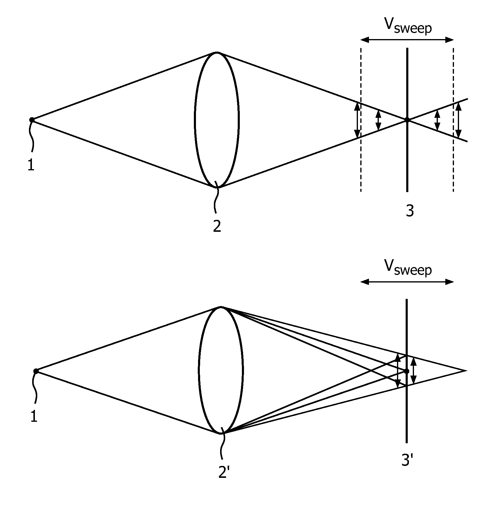
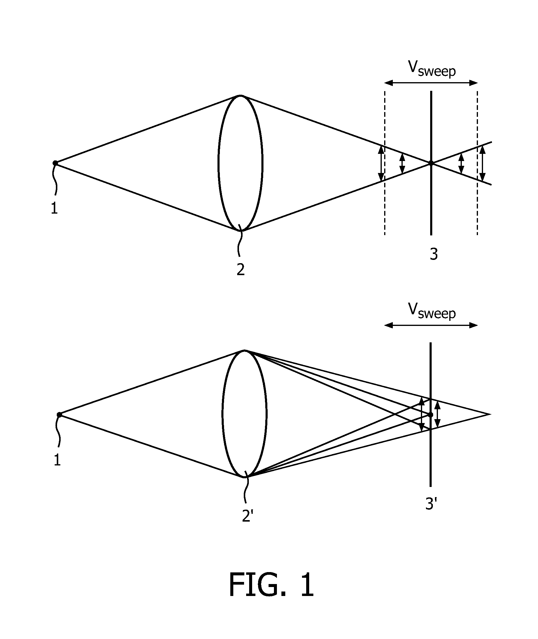
[0057]The invention is based on the insight that by changing the camera parameters during the exposure time, the characteristics of the recorded image can be modified. This is exploited to design a camera of which the motion blur is, within a practical speed range, almost independent of the motion of the objects and preferably one of which the frequency behaviour is such that the recorded signal is better suited for inverse filtering. This allows sharp images to be generated from longer exposure time recordings without the need for motion estimation. In other words, the camera in accordance with the invention can provide sharp images with high SNR even for very challenging optical imaging conditions: objects moving at various, unknown velocities under low illumination levels. To this end the sensor and / or the lens is, during the exposure time, moved along the optical axis, or alternatively or in addition, the focal length of the lens is modified during the exposure time. Changing th...


PUM


Abstract

A camera and system comprising a camera in which, during exposure, the ratio of the distance between the lens and the sensor and the focal length is changed. The rate of change is set such that motion invariant imaging is achievable for practical speed ranges, i.e. speed of up to at least 5 km / hour at 2 meter distance of the lens, by deconvoluting the compound image. Preferably the achievable speed range is at least twice as high. A linear motion of the sensor is preferred.

Description

FIELD OF THE INVENTION[0001]The invention relates to a camera comprising a lens and an image sensor wherein the ratio of the distance between the sensor and the lens along the optical axis and the focal length of the lens is changed during the exposure time of the image. The invention also relates to a method for deconvoluting image data captured by an image sensor.BACKGROUND OF THE INVENTION[0002]Conventional image sensors, such as CMOS and CCD sensors, integrate all light that impinges on them during the exposure time. This provides sharp images of static objects, but results in spatial blur for objects that move while the shutter is open. Objects that are not in focus are also blurred. The so-called motion blur is proportional to the exposure time and object velocity. The former is particularly troublesome when a camera operates under low light level conditions. Under such circumstances, long exposure times are desired to attain sufficiently high signal-to-noise levels such that ...

Claims


Application Information

Patent Timeline
Patent Type & Authority Patents(United States)
IPC IPC(8): G03B13/00G03B7/00
CPCG06T5/003H04N5/23248G06T2207/20201H04N23/68
Inventor MUIJS, REMCO THEODORUS JOHANNESZNAMENSKIY, DMITRY NIKOLAEVICHSCHMEITZ, HAROLD AGNES WILHELMUSVLUTTERS, RUUDVAN HEESCH, FRANCISCUS HENDRIKUS
Owner KONINK PHILIPS ELECTRONICS NV
Why Eureka
Try Eureka