

Method and system for workitem synchronization
a workitem and workitem technology, applied in the field of workitem synchronization, can solve the problems of insufficient synchronization model in opencl, inability to handle such dynamic behavior of workitems, and inability to meet the needs of workitems that are not traditional graphics processing tasks, etc., to achieve the effect of improving processing efficiency and flexibility in programming, and more efficient and flexible scheduling of workitems
- Summary
- Abstract
- Description
- Claims
- Application Information
AI Technical Summary
Benefits of technology
Problems solved by technology
Method used
Image

Examples
Embodiment Construction
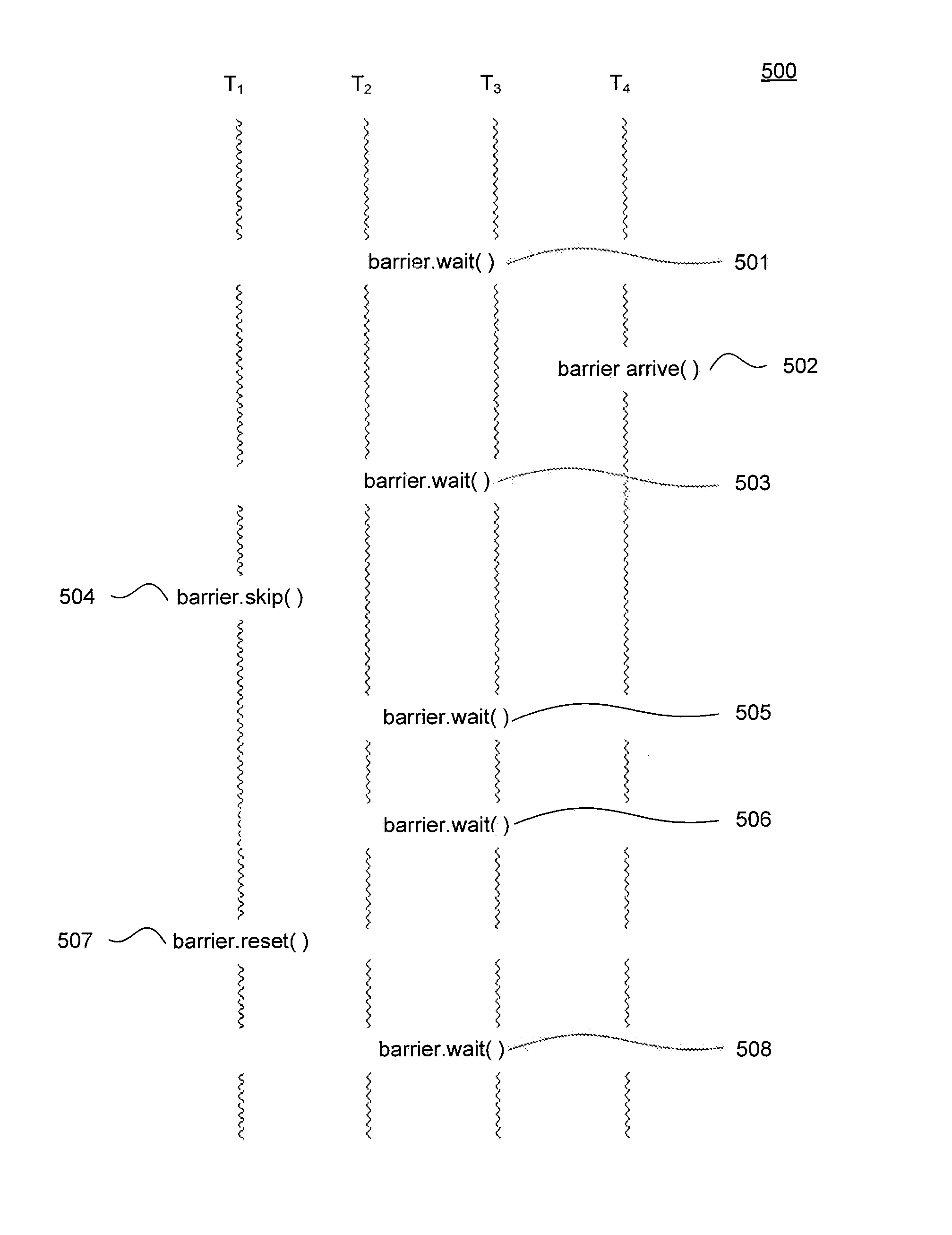
[0015]Methods and systems for more efficient and flexible scheduling of workitems are disclosed. A technique is disclosed for a workitem to indicate that it is permanently leaving a synchronization group such that subsequent barriers that occur in the execution of workitems in that synchronization group do not wait for the workitem that had announced its departure from the group. A further technique is disclosed by which a workitem can rejoin the synchronization group in order to continue to synchronize with other workitems of that group. The disclosed techniques may yield substantial advantages in improved processing efficiency and flexibility in programming in various situations.
[0016]The disclosed method, system, and computer program product embodiments include executing a barrier skip instruction by a first workitem from the group, and responsive to the executed barrier skip instruction, reconfiguring a barrier to synchronize other workitems from the group in a plurality of poin...
PUM
 Abstract
Description
Claims
Application Information