
Damaged fastener extractor

a fastener and extractor technology, applied in the direction of wrenches, screwdrivers, manufacturing tools, etc., can solve the problems of not providing the combination of features and advantages presented in the instant disclosure, its removal, and not providing the combination of features and advantages, so as to optimize the longevity of the damaged fastener extractor, optimize the ability to transfer force, and optimize the disposition and positioning of engagement grooves

Active Publication Date: 2013-12-17
STAWARSKI RAFAL
View PDF49 Cites 12 Cited by
  • Summary
  • Abstract
  • Description
  • Claims
  • Application Information

AI Technical Summary

Benefits of technology

[0067]Thus, it is an object of the present disclosure to provide, in combination with the other features and advantages disclosed herein, a geometry of the damaged fastener engagement aperture to facilitate convenient selection of the appropriate tool to be used to turn the damaged fastener extractor.
[0068]Yet another object of the present disclosure is to provide, in combination with the other features and advantages disclosed herein, an optimal disposition and positioning of engagement grooves to effectuate relatively uniform engagement of all corners of a damaged fastener to be extracted.
[0069]Still a further object of the present disclosure is to provide, in combination with the other features and advantages disclosed herein, a selectable geometry of engagement grooves to optimize the ability to transfer force from a tool through the damaged fastener extractor to the damaged fastener to be extracted.
[0070]An additional object of the present disclosure is to provide, in combination with the other features and advantages disclosed herein, a selectable geometry of grooves to optimize longevity of the damaged fastener extractor.
[0071]Another object of the present disclosure is to provide, in combination with the other features and advantages disclosed herein, a selectable angle of inward taper to the engagement grooves to permit ease of use with different shaped damaged fasteners.
[0073]The following disclosure provides a damaged fastener extractor that provides the foregoing advantages while at the same time is relatively low in cost to manufacture and possesses extended durability.

Problems solved by technology

As can be seen, there are a vast array of efforts already existing to provide a solution to the problems confronted when removing damaged fasteners, but none provides the combination of features and advantages presented in the instant disclosure.
U.S. Pat. No. 4,947,712 generally discloses a wrench-type socket for removing bolts and the like whose head has become damaged or otherwise worn, thus prohibiting its removal by the use of a conventional socket.
Thus, a problem associated with devices that precede the present disclosure is that they do not provide, in combination with the other features and advantages disclosed herein, a geometry of the damaged fastener engagement aperture to facilitate convenient selection of the appropriate tool to be used to turn the damaged fastener extractor.
Yet another problem associated with devices that precede the present disclosure is that they do not provide, in combination with the other features and advantages disclosed herein, the optimal disposition and positioning of engagement grooves to effectuate relatively uniform engagement of all corners of a damaged fastener to be extracted.
Still a further problem associated with devices that precede the present disclosure is that they do not provide, in combination with the other features and advantages disclosed herein, a selectable geometry of engagement grooves to optimize the ability to transfer force from a tool through the damaged fastener extractor to the damaged fastener to be extracted.
An additional problem associated with devices that precede the present disclosure is that they do not provide, in combination with the other features and advantages disclosed herein, a selectable geometry of grooves to optimize longevity of the damaged fastener extractor.
Another problem associated with devices that precede the present disclosure is that they do not provide, in combination with the other features and advantages disclosed herein, a selectable angle of inward taper to the engagement grooves to permit ease of use with different shaped damaged fasteners.
An even further problem associated with devices that precede the present disclosure is that they do not provide, in combination with the other features and advantages disclosed herein, a selectable angle of axial orientation of the engagement grooves to permit optimal force transfer from a tool through the damaged fastener extractor to the damaged fastener to be extracted.

Method used


Image

  • Damaged fastener extractor
  • Damaged fastener extractor
  • Damaged fastener extractor

Examples


Embodiment Construction

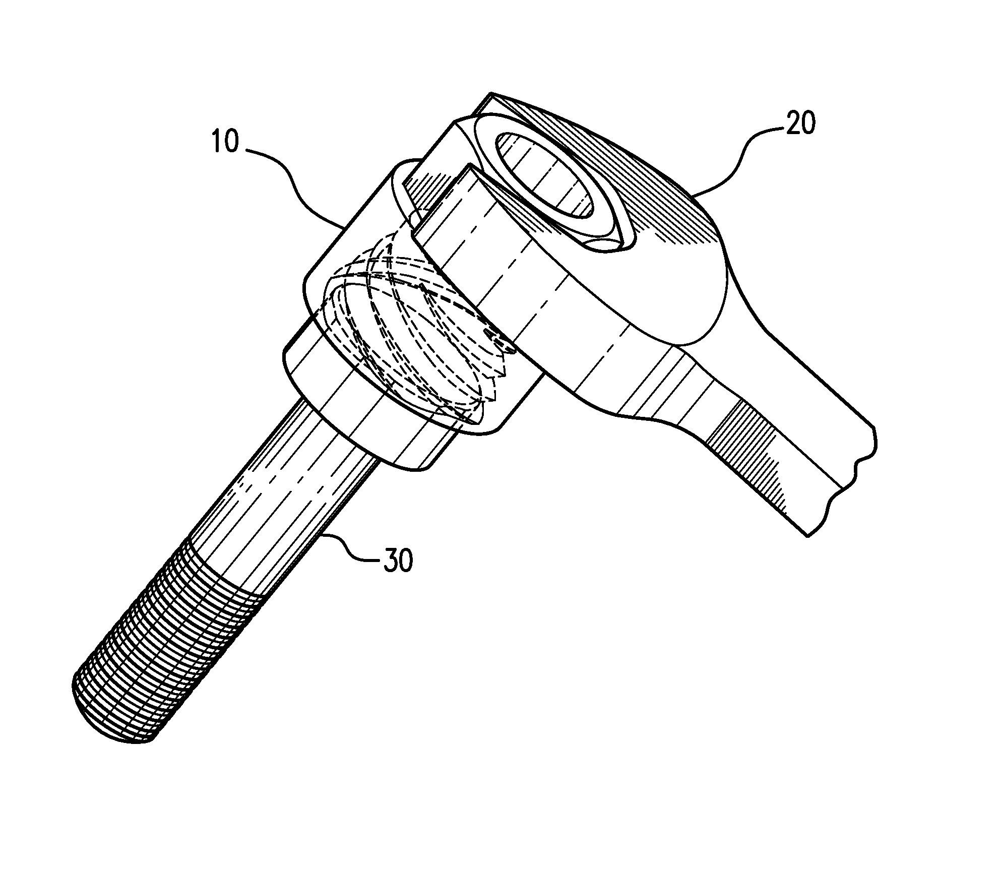
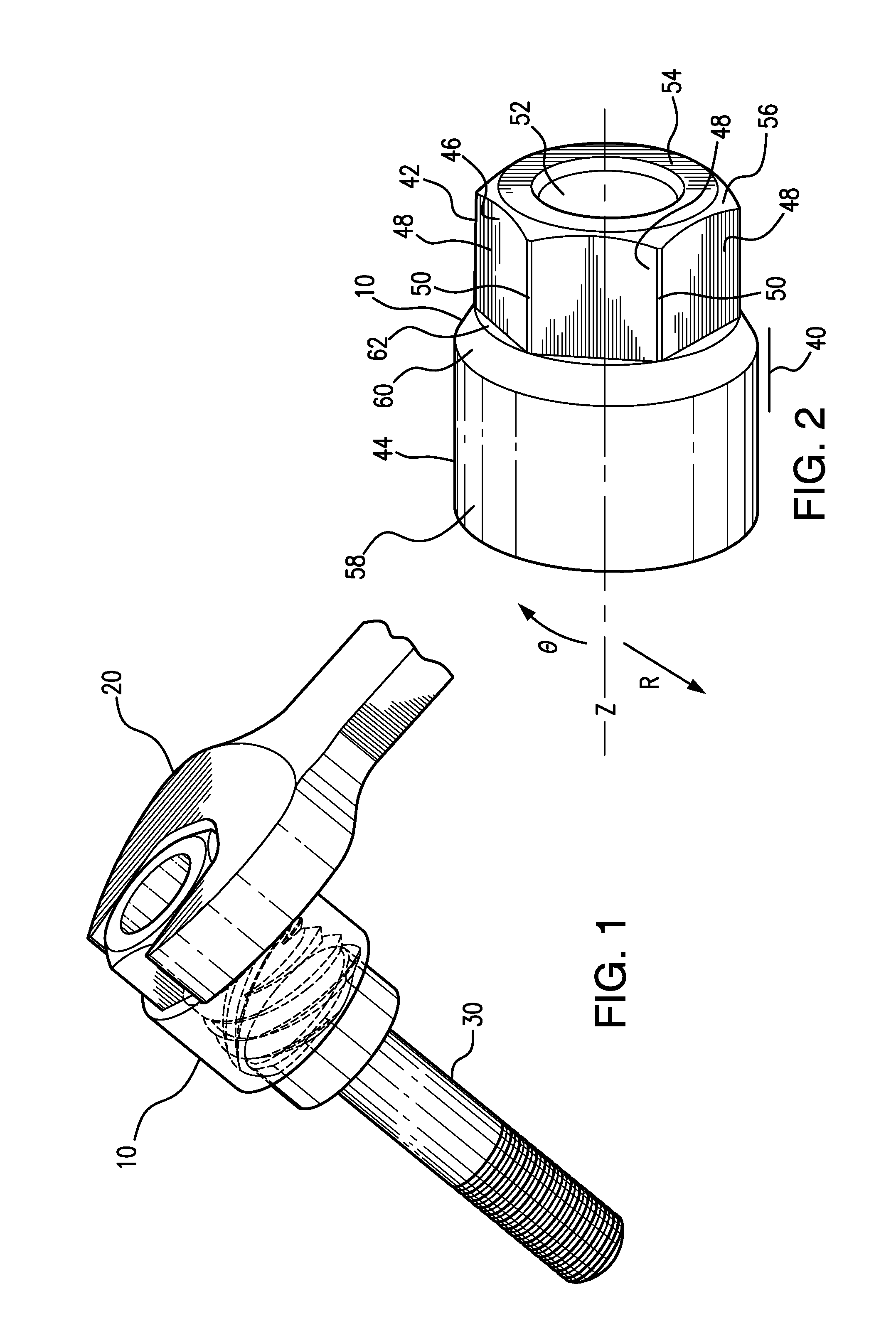
[0089]As shown in FIG. 1 a damaged fastener extractor 10 is provided for use with a tool 20 to remove a damaged fastener 30. The tool 20, which as shown is an open end wrench, is fitted over the damaged fastener extractor 10 and transmits torque through the extractor 10 to the damaged fastener 30, thereby effecting its removal.

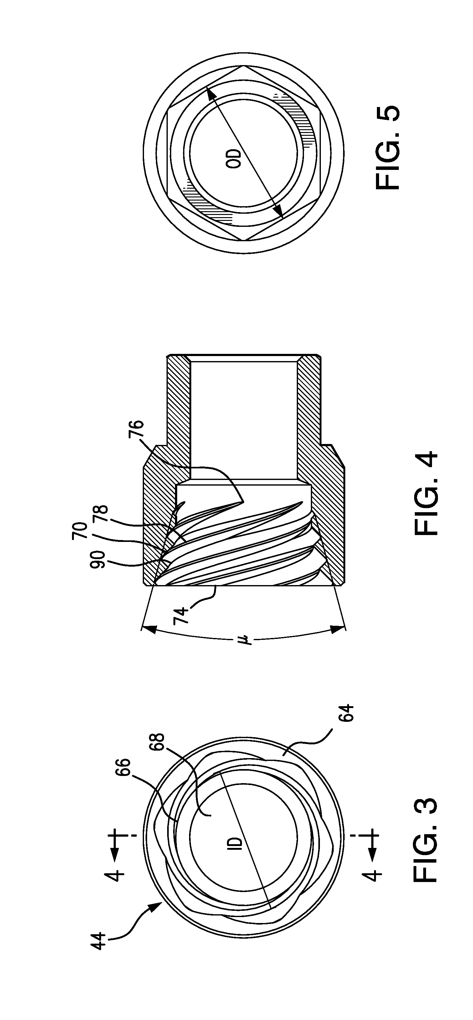
[0090]As shown in FIG. 2, the extractor 10 has a body 40 defining generally cylindrical coordinates ⊖, Z and R about an axis and having a rear body portion 42 communicating with a front body portion 44. The rear body portion 42 has an outer surface 46 shaped to be engaged by the tool 20 to be used to rotate the body 40 circumferentially about the axis.

[0091]The rear body portion outer surface 46 is shaped hexagonally and has six sides 48. The sides 48 are spaced apart to present a working outer dimension OD to the tool 20 (see FIG. 5). The sides 48 have axial bevel regions 50 therebetween for durability and to reduce the sharpness of the extractor 10 to the us...


PUM


Abstract

A damaged fastener extractor is provided with a body defining generally cylindrical coordinates ⊖, Z and R about an axis and having a rear body portion communicating with a front body portion. The rear body portion has an outer surface shaped to be engaged by a tool to be used in rotating the body circumferentially about the axis and sized to present a working outer dimension OD to said tool. The front body portion has a front terminus and an inner surface in which the front terminus is oriented substantially perpendicular to the axis and provides a generally circular receiving aperture communicating with the inner surface. The inner surface is shaped to engage a damaged fastener to be extracted and sized to present a working inner diameter ID to the damaged fastener. The front body portion inner surface has equally spaced, parallel grooves positioned thereon and oriented to extend along an arcuate, inwardly tapering path from a forward groove terminus located proximal to the front body portion front terminus to a rearward groove terminus located proximal to the rear body portion. Each groove has a centerline extending along its length and a pitch P defined by the axial displacement of the centerline per revolution of the centerline about the axis. Each groove further has a substantially constant cross-sectional geometry extending along most of its length, whereby the position of each groove centerline at the forward terminus is ⊖1, Z1 and R1 and the position of each groove centerline at the rearward terminus is ⊖2, Z2 and R2. Due to the inward taper, R1 is greater than ID / 2 which is greater than R2, and an angle of inward taper μ is defined by tan μ=(R1−R2) / (Z1−Z2).

Description

CROSS REFERENCE TO RELATED APPLICATIONS[0001]This application claims priority to U.S. provisional patent application Ser. No. 61 / 444,332, filed Feb. 18, 2011.FIELD OF THE INVENTION[0002]A damaged fastener extractor is disclosed. In a preferred embodiment, the damaged fastener extractor is provided with a body defining generally cylindrical coordinates about an axis and having a rear body portion communicating with a front body portion. The rear body portion has an outer surface shaped to be engaged by a tool to be used in rotating the body circumferentially about the axis and sized to present a working outer dimension OD to said tool. The front body portion has a front terminus and an inner surface in which the front terminus is oriented substantially perpendicular to the axis and provides a generally circular receiving aperture communicating with the inner surface. The inner surface is shaped to engage a damaged fastener to be extracted and sized to present a working inner dimensio...

Claims


Application Information

Patent Timeline
Patent Type & Authority Patents(United States)
IPC IPC(8): B25B13/50B25B13/06B25B23/08
CPCB25B27/18
Inventor STAWARSKI, RAFAL
Owner STAWARSKI RAFAL
Learn More