Rear suspension for three-wheeled car

a three-wheeled car and rear suspension technology, applied in the direction of steering linkages, bicycles, transportation and packaging, etc., can solve the problems of reducing stability, reducing stability, and swing-arm suspension structure having a tendency to toe out, so as to achieve greater stability

Active Publication Date: 2013-12-17
HYUNDAI MOTOR CO LTD
View PDF36 Cites 10 Cited by
  • Summary
  • Abstract
  • Description
  • Claims
  • Application Information

AI Technical Summary

Benefits of technology

[0014]Various aspects of the present invention are directed to providing a rear suspension of a three-wheeled car with greater stability when the car is turning, by inducing the changes in the toe angle and the camber angle of the rear wheel forcibly when the car is turning.
[0032]The rear suspension structure of the present invention as described above is a structure that induces toe-in in the rear wheel to induce under-steer of the car as the car turns, i.e. a structure in which the rear wheel turns in the same direction the front wheels turn, and therefore, it can prevent spin-outs and bring the anti-roll effect, which can enhance the stability when the car is turning.
[0033]In addition, a roll connector and a knuckle assembly have a structure where the rotating force is conveyed through a roll shaft, which makes it possible for the structure of the present invention to be applied regardless of how long the car body frame is.
[0034]The knuckle assembly can not only turn left and right but also up and down in connection with the damping strut not depicted in the drawings so it can buffer the impact coming from the ground, and also it can be installed in the curvature formed in the rear part of the car body frame so the height of the car body frame from the ground is smaller.
[0035]Also, a pair of the roll links is arranged in the left side and the right side of the car body frame respectively, and they are connected to each other by a ball joint so the roll connector can revolve around the shaft more efficiently.
[0036]The rear suspension structure of a second embodiment of the present invention is a structure in which the toe angle and the camber angle of the rear wheel change automatically to induce under-steer of the car as the car turns, and therefore, it can prevent spin-outs and enhance more efficiently the stability of the car when the car is turning.

Problems solved by technology

Compared to a four-wheeled vehicle, a three-wheeled car has the advantage of being lighter and more fuel-efficient, and yet, it has the disadvantage of having less stability while on the road.
In other words, there was the problem of diminished stability when a three-wheeled car is turning.
Also, the swing-arm type suspension structure had a tendency for a toe-out when the lateral force is applied, due to the compliance effect the effect as though the handle is being steered when the external forces change the forms of rubber bushes for suspension and hence change the alignment.
Thus, the stability of a car when it is turning is significantly reduced if it uses a swing-arm type suspension such as the one described above due to the centrifugal force and the lateral force which induce the over-steer moment.
Hence, there is the problem of a rear wheel breaking away from the right track and the stability of a car decreasing when a car is on the road.

Method used


Image

  • Rear suspension for three-wheeled car
  • Rear suspension for three-wheeled car
  • Rear suspension for three-wheeled car

Examples


first embodiment

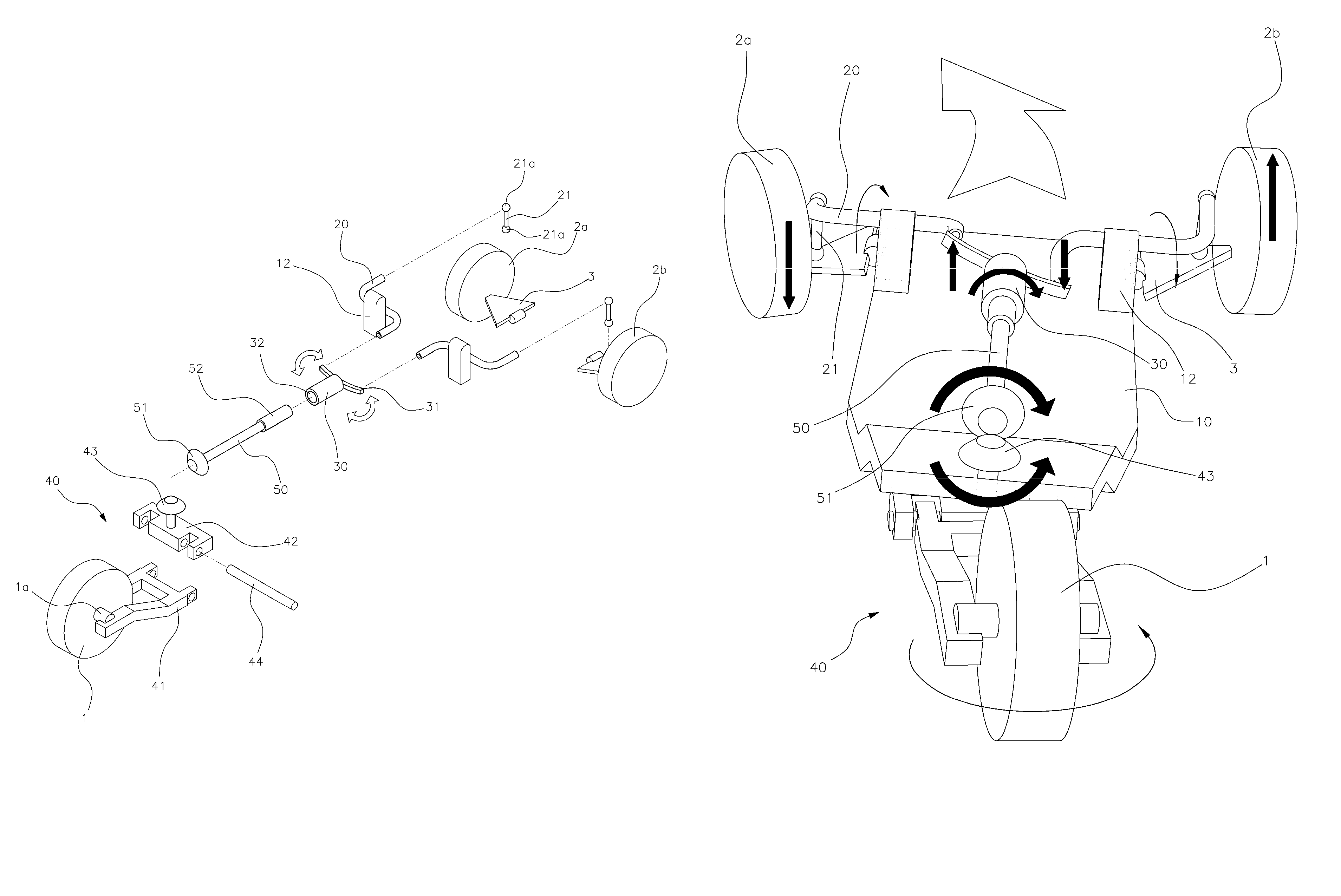
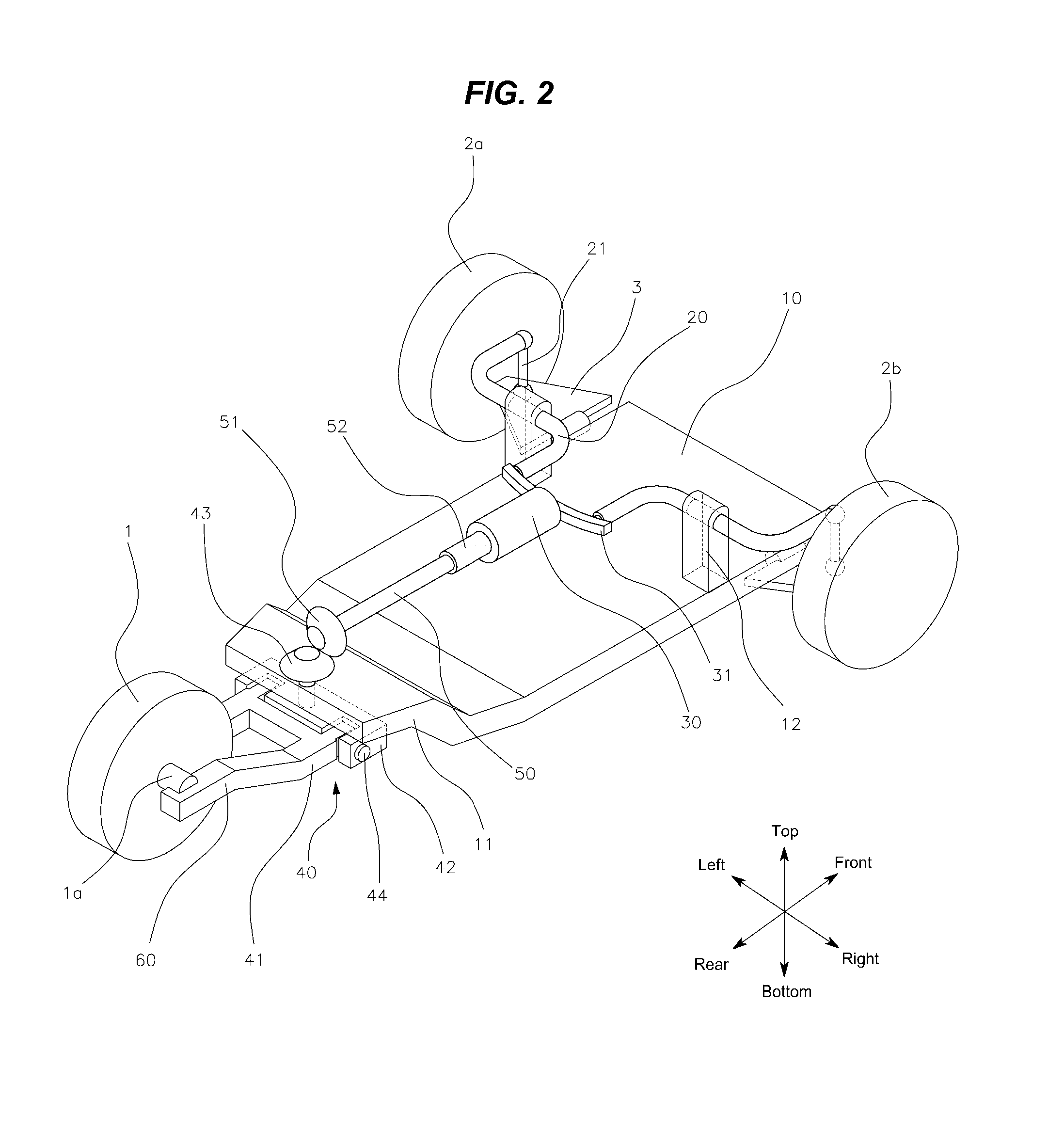
[0053]In reference to FIG. 2 and FIG. 3, a car body frame 10, according to the present invention, has a pre-determined area, and two front wheels 2a, 2b are installed in its front part, one on the left and the other on the right. Each of the front wheels 2a, 2b is connected to the car body frame 10 through a lower arm 3, which revolves up and down as the car turns.

[0054]In addition, each lower arm 3 is connected to a roll link 20 through a drop link 21. The roll link 20 is a bar with a bent shape of an “S” and is installed in a way that it can be twisted around the mount component 12 with the mount component 12 as a shaft. In other words, a roll link 20, which is installed in the mount component 12 and receives the force through a drop link 21, performs a twisting movement, in which, if one end of the roll link 20 connected to the drop link 21 moves downward, the other end moves upward, and if one end of the roll link 20 connected to the drop link 21 moves upward, the other end move...

second embodiment

[0064]In reference to FIG. 6 and FIG. 7, a car body frame 10, according to the present invention, has a pre-determined area, and two front wheels 2a, 2b are installed in its front part, one on the left and the other on the right. Each of the front wheels 2a, 2b is connected to the car body frame 10 through a lower arm 3, which revolves up and down as the car turns.

[0065]As in a first embodiment, each lower arm 3 is connected to a roll link 20 through a drop link 21. The roll link 20 is a bar with a bent shape of an “S” and is installed in a way that it can be twisted around the mount component 12 with the mount component as a shaft.

[0066]A knuckle assembly 40 is installed in the rear end of the car body frame 10 in a way that it rotates in the same direction the front wheels 2a, 2b turn and changes the toe angle, but as it changes the toe angle, it rotates around a shaft and changes the camber angle of the rear wheel as well.

[0067]The knuckle assembly 40 includes a combination of a ...


PUM


Abstract

A rear suspension of a three-wheeled car with two front wheels and one rear wheel installed in the car body frame may include a pair of roll links that may be connected to the front wheels and twists as the car turns, and a roll connector that pivots around a shaft as the roll links twist, and a knuckle assembly, which may be joined to a rear wheel, installed in the rear end of the car body frame, and connected to a roll connector so that it turns left and right as the roll connector turns, wherein the knuckle assembly turns in the same direction the front wheels turn.

Description

CROSS-REFERENCE TO RELATED APPLICATION[0001]The present application claims priority to Korean Patent Application No. 10-2011-0117473, filed on Nov. 11, 2011 and to Korean Patent Application No. 10-2011-0132760, filed on Dec. 12, 2011, the entire contents of which is incorporated herein for all purposes by this reference.BACKGROUND OF THE INVENTION[0002]1. Field of the Invention[0003]The present invention relates to a rear suspension for a three-wheeled car, and more particularly, to a rear suspension for a three-wheeled car, which comprises two front wheels and one rear wheel, in which the steering in the rear wheel is automatically adjusted by the tow angle and camber angle, which are adjusted by the direction the car is turning so that the stability is enhanced when the car is turning.[0004]2. Description of Related Art[0005]Currently, the efforts to improve the fuel efficiency of a car are being made continuously and globally. As a part of making such efforts, the studies on impr...

Claims


Application Information

Patent Timeline
Patent Type & Authority Patents(United States)
IPC IPC(8): B62D61/06
CPCB60G3/00B62K5/08B60G3/26B60G3/145B60G2200/44B60G2300/122B60G2300/45
Inventor LEE, SANG-HOONLEE, JAE-KIL
Owner HYUNDAI MOTOR CO LTD
Why Eureka
Try Eureka