Liquid discharge head and ink jet recording apparatus including liquid discharge head

a liquid discharge head and ink jet recording technology, applied in other printing apparatus, printing, etc., can solve the problems of inability to control inability to control the noise of inductive coupling, and the failure of the driving circuit, so as to increase the speed of recording operation and avoid the effect of nois

Active Publication Date: 2013-12-17
CANON KK
View PDF75 Cites 32 Cited by
  • Summary
  • Abstract
  • Description
  • Claims
  • Application Information

AI Technical Summary

Benefits of technology

[0010]According to the above configuration, each of the pair of lines for temperature detection for applying the second current to the temperature detecting element is arranged adjacent to the other. Therefore, when the first current is fed to the heat generating element while feeding the second current to the temperature detecting element regularly, each of the pair of lines for temperature detection receives the noise emitted from the electrical power source line and the grounding line in the same environment (positions) as each other. At this time, since noise currents which flow through the pair of lines for temperature detection, respectively, have reverse phases as seen from the temperature detecting element, these noise currents are mutually cancelled out. Therefore, the noise currents generated in the pair of lines for temperature detection during current application of both the temperature detecting element and the heat generating element are suppressed. Thereby, temperature detection which is not easily influenced by noise even during recording is possible, and it is possible to further increase the speed of recording operation.

Problems solved by technology

As such a pulsed large current flows, noise caused by inductive coupling may be generated in a signal line of the above driving circuit.
In this case, there is a concern that the driving circuit may malfunction due to the noise.
Therefore, it is assumed that noise is generated in an electrical line for applying a current to the temperature detecting element.
In this case, there is a concern that the output voltage of the temperature detecting element may be influenced by noise, and the temperature of the heat generating element may be erroneously detected.
In addition, although Japanese Patent Application Laid-Open No. 2000-127400 discloses a technique in which a driving circuit is not easily influenced by noise, a technique of coping with erroneous detection of the temperature of the heat generating element described above is not disclosed.

Method used


Image

  • Liquid discharge head and ink jet recording apparatus including liquid discharge head
  • Liquid discharge head and ink jet recording apparatus including liquid discharge head
  • Liquid discharge head and ink jet recording apparatus including liquid discharge head

Examples


Embodiment Construction

[0022]An exemplary embodiment of the present invention will now be described in detail in accordance with the accompanying drawings.

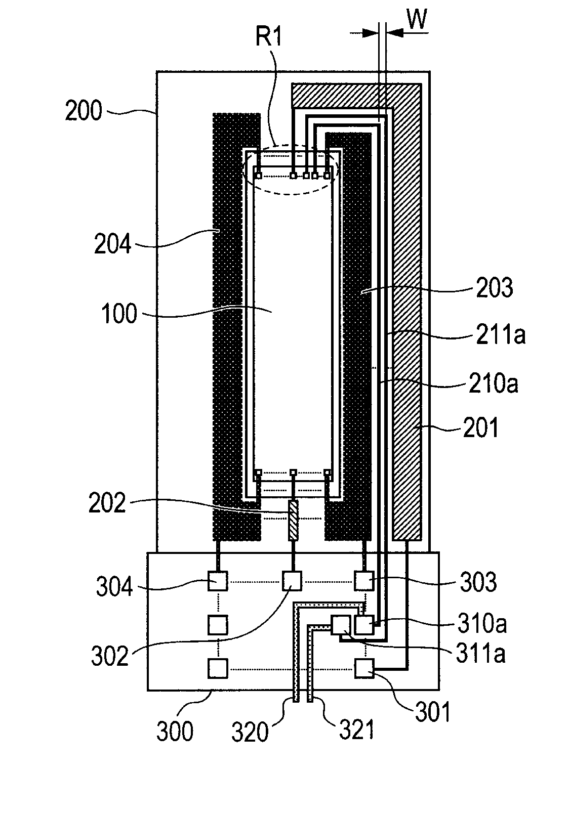
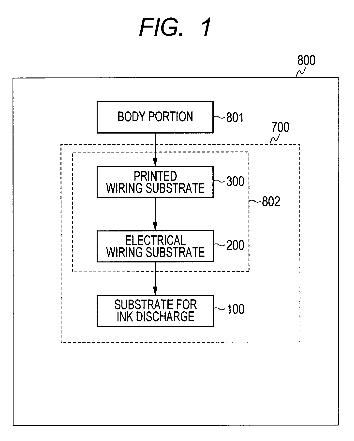
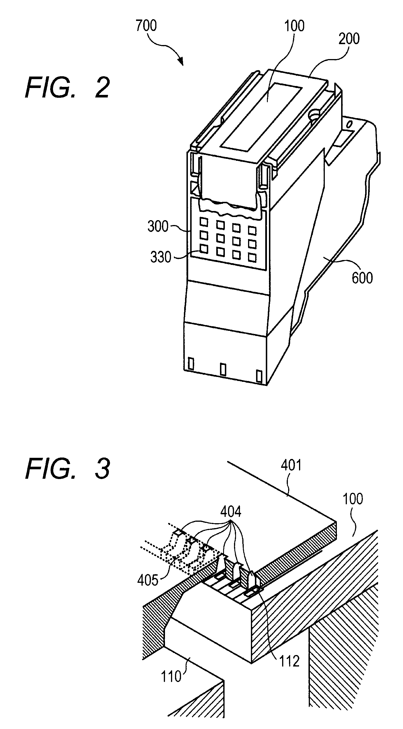
[0023]FIG. 1 is a block diagram illustrating an electric configuration of an ink jet recording apparatus of the present embodiment. As illustrated in FIG. 1, an ink jet recording apparatus 800 of the present embodiment has a liquid discharge head 700 which discharges ink, and a body portion 801 electrically connected to the liquid discharge head 700. The liquid discharge head 700 has a recording element substrate 100, and an electrical wiring member 802 electrically connected to the recording element substrate 100. The electrical wiring member 802 has an electrical wiring substrate 200 and a printed wiring substrate 300.

[0024]The recording element substrate 100 is electrically connected to the electrical wiring substrate 200. Additionally, connecting terminals are provided in the same shape on both the electrical wiring substrate 200 and a printed wirin...


PUM


Abstract

A liquid discharge head includes a heat generating element which generates heat energy used to discharge a liquid; a temperature detecting element which changes in output voltage in response to a change in the temperature of the heat generating element; an electrical power source line and a grounding line electrically connected to each other through the heat generating element to apply a current to the heat generating element; and a pair of lines for temperature detection electrically connected to each other through the temperature detecting element to apply a current to the temperature detecting element. Here, each of the pair of lines for temperature detection is arranged adjacent to the other.

Description

BACKGROUND OF THE INVENTION[0001]1. Field of the Invention[0002]The present invention relates to a liquid discharge head which discharges liquids, such as ink, and an ink jet recording apparatus including the liquid discharge head.[0003]2. Description of the Related Art[0004]As liquid discharge heads provided in an ink jet recording apparatus, there is a liquid discharge head in which a heat generating element (heater) and its driving circuit, and line which connects the heat generating element and the driving circuit are formed on the same substrate, using a semiconductor processing technique. Moreover, there is also a liquid discharge head in which a temperature detecting element which is close to a heat generating element and in which an output voltage changes in response to the temperature change of the heat generating element is formed.[0005]In ink jet recording apparatuses including the above liquid discharge heads, in order to increase the speed of recording operation, the nu...

Claims


Application Information

Patent Timeline
Patent Type & Authority Patents(United States)
IPC IPC(8): B41J29/393
CPCB41J2/04563B41J2/14072B41J2/0458B41J2/1603B41J2/16B41J2/14024B41J2/2142
Inventor OOHASHI, RYOJIIMANAKA, YOSHIYUKIMASUDA, KAZUNORISEKIJIMA, DAISHIROAOKI, TAKASHI
Owner CANON KK
Why Eureka
Try Eureka