LED light module with heat releasing casing and grooved backing to contain conductive bonding fluids

a technology of led light modules and conductive bonding fluids, which is applied in the direction of lighting and heating apparatus, semiconductor devices for light sources, and light support devices. it can solve the problems of deteriorating voltage resistance, deformation of base materials, and common problems of conventional structures b>150/b> and b>160/b>, so as to prevent an increase in labor costs and prevent quality deterioration , the effect of efficient thermal releas

Inactive Publication Date: 2013-12-17
PANASONIC CORP
View PDF4 Cites 0 Cited by
  • Summary
  • Abstract
  • Description
  • Claims
  • Application Information

AI Technical Summary

Benefits of technology

[0018]In one aspect, a lighting structure is provided that is capable of performing efficient thermal release and also preventing an increase labor costs, providing cost advantages, and also preventing quality deterioration. In one embodiment, the structure is included in a light fixture.
[0026]In another aspect, in a lighting structure and a light fixture that incorporates the structure, heat is radiated efficiently and an increase in labor costs is prevented, cost advantages are provided, and heat deterioration is prevented.

Problems solved by technology

However, such conventional structures 150 and 160 have a common problem.
To solve such a conventional problem, application of a base material of metal using a material such as copper or aluminum improves heat release performance of the LED package but deteriorates the voltage resistance because the thickness of the insulation layer of the base material is small.
However, this heat conducting sheet is soft itself and thus flexure occurs between a screw-fixed portion and a screw-non-fixed portion, thereby causing deformation of the base material, which raises a long-term reliability problem.
In addition, heat conductivity of the heat conducting sheet with high voltage resistance is not high, thus impeding heat conduction in some cases.
A small gap is created between the metal material and a hard material having both thermal conductance and electric insulation properties which impedes heat release due to the thermal insulating effect of air.
Further, even when the extension due to the thermal expansion is minimized following the automatic firm fixation, the small gap is created by, for example, the slight deformation of the metal base material, which impedes the heat release.
However, the excess plastic fluid or adhesive agent protrudes from the margins of the LED package, which therefore requires an additional material removal process, resulting in an increase in labor costs.

Method used


Image

  • LED light module with heat releasing casing and grooved backing to contain conductive bonding fluids
  • LED light module with heat releasing casing and grooved backing to contain conductive bonding fluids
  • LED light module with heat releasing casing and grooved backing to contain conductive bonding fluids

Examples


Embodiment Construction

[0041]Hereinafter, structures and light fixtures provided respectively with the structures according to a plurality of embodiments of the present invention will be described referring to the drawings.

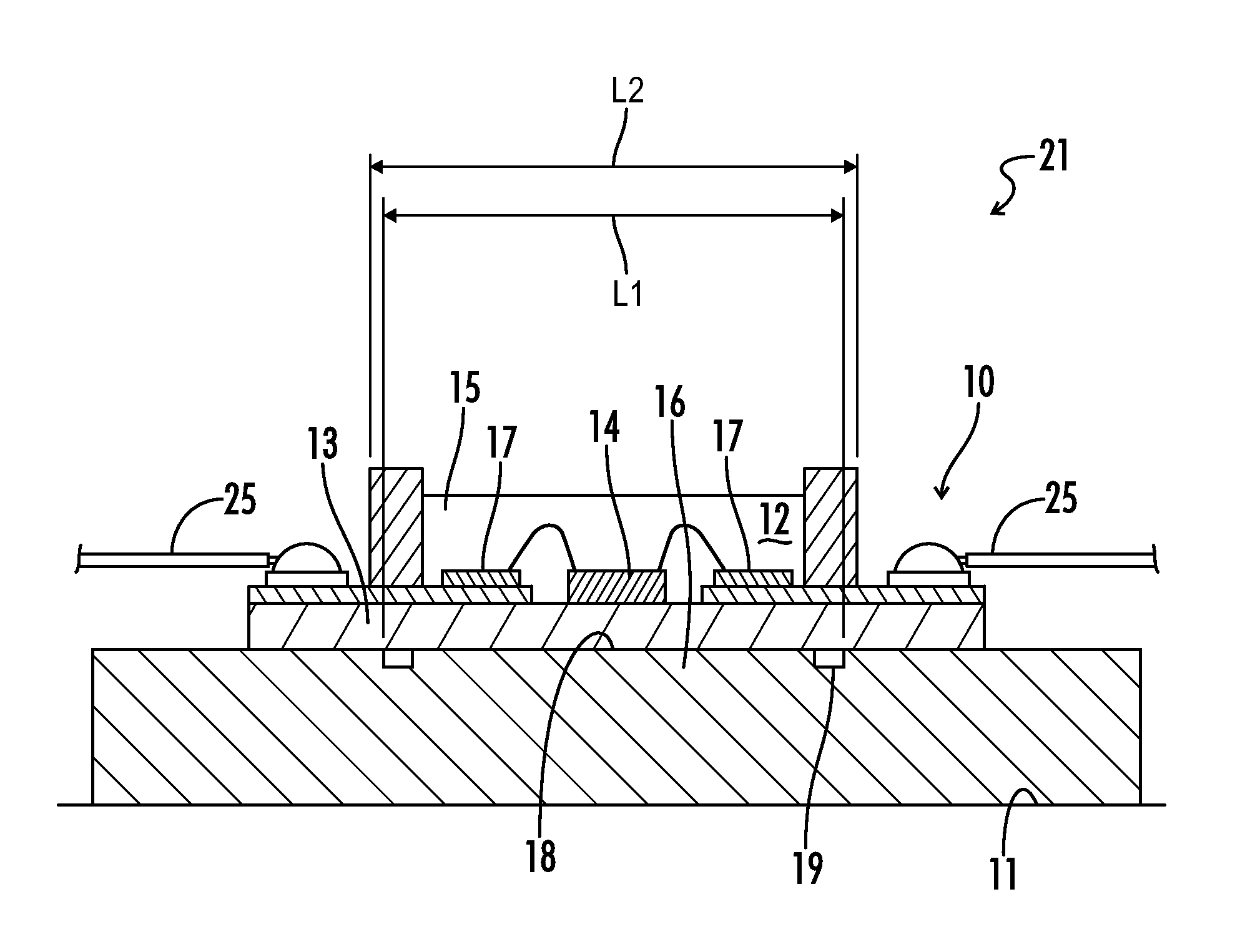
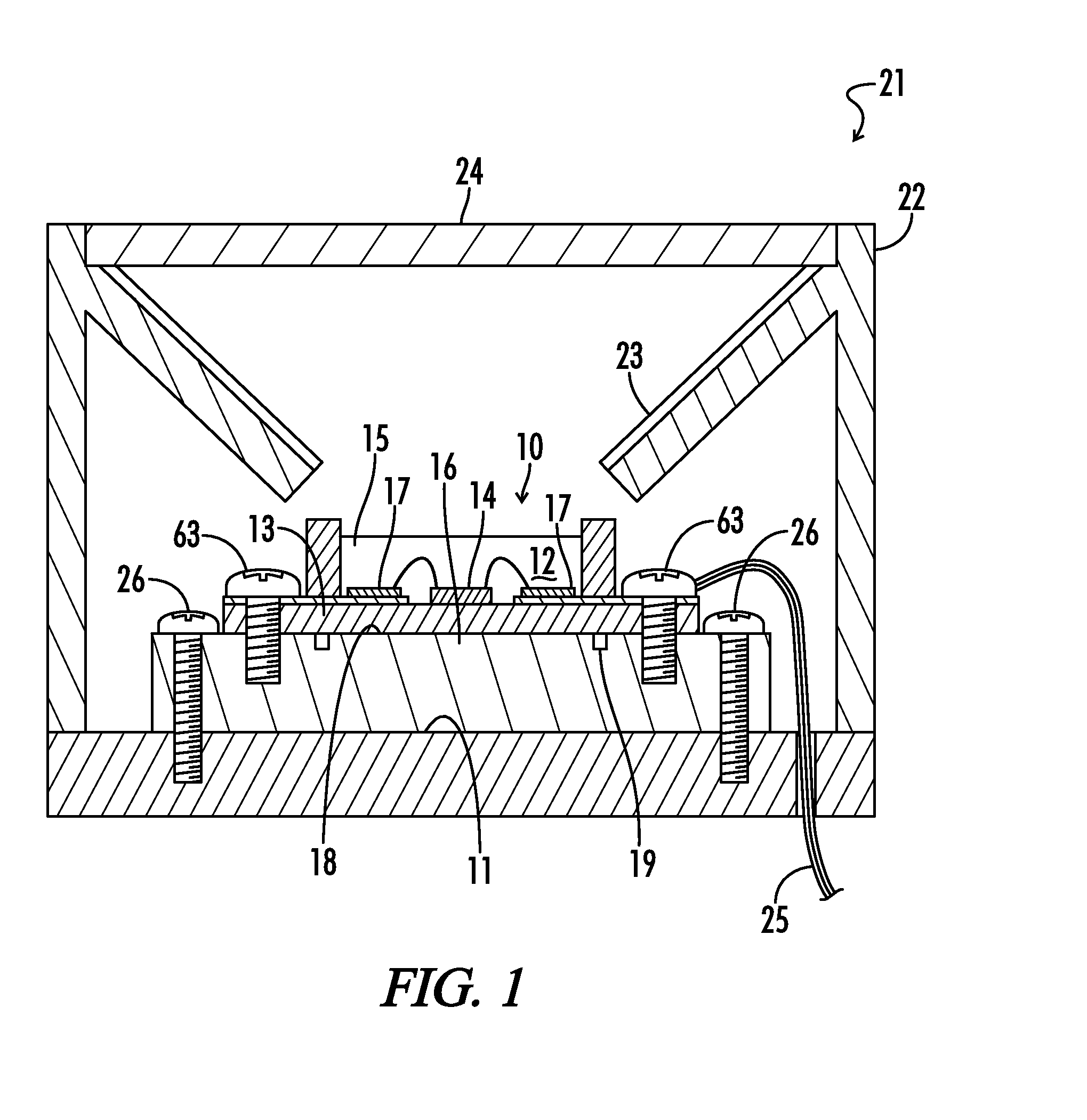
[0042]As shown in FIG. 1, one embodiment of a light fixture 21 that incorporates a lighting structure (LED module) 10 includes a fixture main body 22, a reflector 23 fitted inside of the fixture main body 22; a lens 24 which is, for example, a transparent or milky white resin and which is fitted to a front surface of the fixture main body 22. The structure or module 10 is attached to a heat releasing casing 11. A wire 25 is provided for feeding power to the structure 10. Screws 26 may be used for connecting the structure 10 to the heat releasing casing 11.

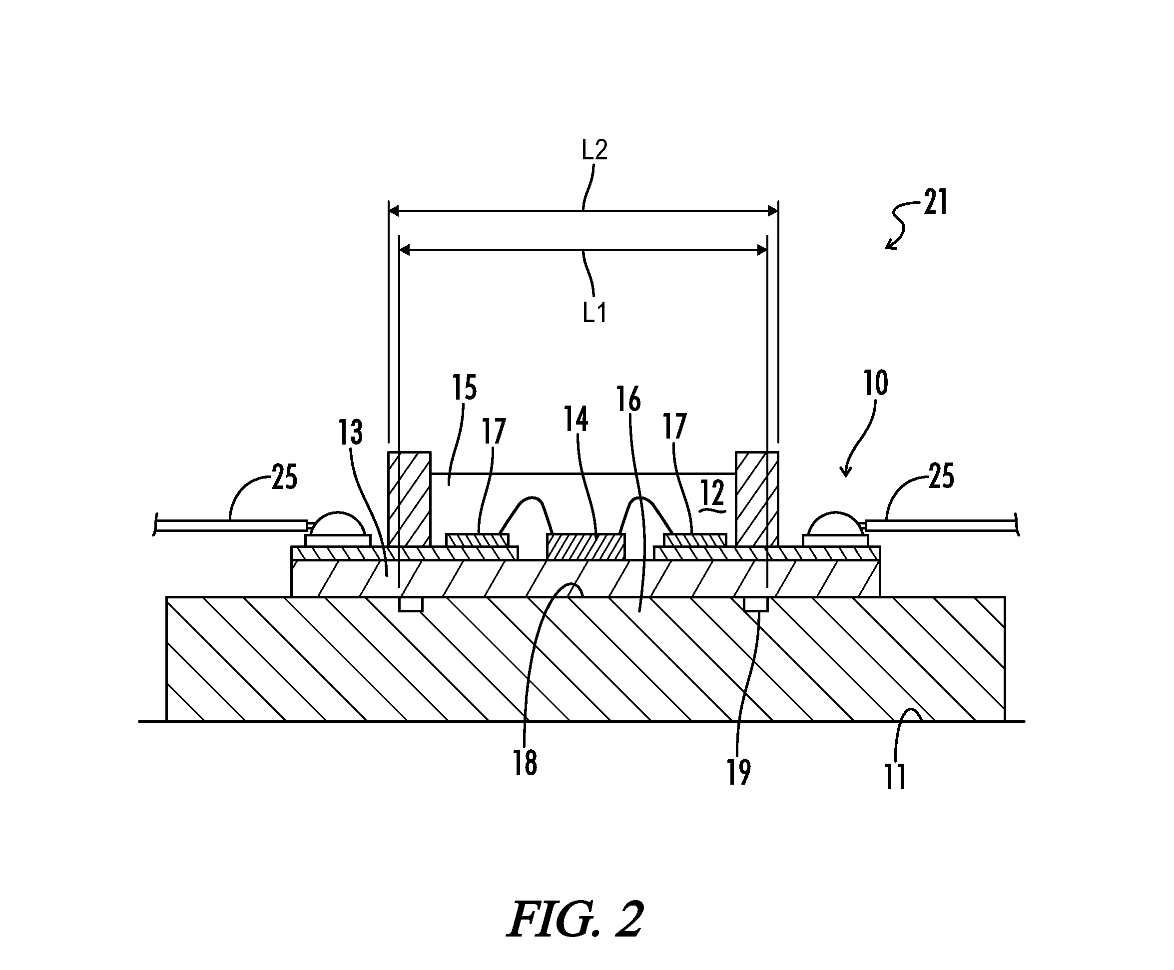
[0043]As shown in FIG. 2, the lighting structure or LED module 10 may include the heat releasing casing 11, an LED package 12 having an LED chip 14 mounted on a base 13 (e.g., a metal base material) and sealed with a sealing material 1...


PUM

PropertyMeasurementUnit
creeping distanceaaaaaaaaaa
temperaturesaaaaaaaaaa
creeping distanceaaaaaaaaaa

Abstract

An LED module structure and a light fixture provided with the structure includes a heat releasing casing; an LED package having an LED chip mounted on a base material, a material having both heat conductance and electric insulation property placed between the heat releasing casing and the LED package upon fitting of the LED package to the heat releasing casing, and a plastic fluid or adhesive agent having particles with high heat conductivity. The material has a groove with outside smaller than an outside dimension of the LED package. The groove receives excess plastic fluid or excess adhesive agent on a surface to which the LED package is firmly attached.

Description

[0001]A portion of the disclosure of this patent document contains material that is subject to copyright protection. The copyright owner has no objection to the reproduction of the patent document or the patent disclosure, as it appears in the U.S. Patent and Trademark Office patent file or records, but otherwise reserves all copyright rights whatsoever.CROSS-REFERENCES TO RELATED APPLICATIONS[0002]This application claims benefit of the following patent application which is hereby incorporated by reference: Japan Patent Application No. 2010-257173, filed Nov. 17, 2010.STATEMENT REGARDING FEDERALLY SPONSORED RESEARCH OR DEVELOPMENT[0003]Not ApplicableREFERENCE TO SEQUENCE LISTING OR COMPUTER PROGRAM LISTING APPENDIX[0004]Not ApplicableBACKGROUND OF THE INVENTION[0005]The present invention relates to a structure having an LED package fixed to a heat releasing casing and a light fixture provided with the structure.[0006]Conventionally, a lighting structure includes a metal fitted membe...

Claims


Application Information

Patent Timeline
Patent Type & Authority Patents(United States)
IPC IPC(8): H01L33/64
CPCF21V19/0055F21Y2101/02H01L2224/48091H01L2924/00014F21Y2115/10Y10T29/49885
Inventor YAMAKAWA, MAMORUTAKASHIMA, JUNUENOYAMA, KOJI
Owner PANASONIC CORP
Why Eureka
Try Eureka