Object detecting apparatus and object detecting method

a technology of object detection and object detection, which is applied in the direction of using reradiation, pedestrian/occupant safety arrangement, instruments, etc., can solve the problems of difficulty in accurately acquiring the edge of the target by means of radar, and the cost is relatively high in order to realize the object detecting apparatus, so as to improve the detection accuracy of the lateral position of the targ

Active Publication Date: 2013-12-17
TOYOTA JIDOSHA KK
View PDF15 Cites 168 Cited by
  • Summary
  • Abstract
  • Description
  • Claims
  • Application Information

AI Technical Summary

Benefits of technology

[0035]According to the present invention, it is possible to further improve the detection accuracy of the lateral position of the target in the object detecting apparatus for detecting the object on the basis of the target information acquired by the radar and the target information acquired from the image picked up by the monocular image sensor.

Problems solved by technology

However, it is difficult to correctly acquire the edge of the target by means of the radar.
However, when the stereo image sensor is used as the image sensor, it is necessary to secure a relatively large space in order to install the stereo image sensor.
Further, the cost is relatively expensive as well in order to realize the object detecting apparatus.

Method used


Image

  • Object detecting apparatus and object detecting method
  • Object detecting apparatus and object detecting method
  • Object detecting apparatus and object detecting method

Examples


Embodiment Construction

[0050]Specified embodiments of the present invention will be explained below on the basis of the drawings. For example, the size, the material, the shape, and the relative arrangement of any constitutive part described in the embodiment of the present invention are not aimed to limit the technical scope of the invention only thereto unless specifically stated.

[0051]A first embodiment of the present invention will be explained on the basis of FIGS. 1 to 9.

(Schematic Arrangement)

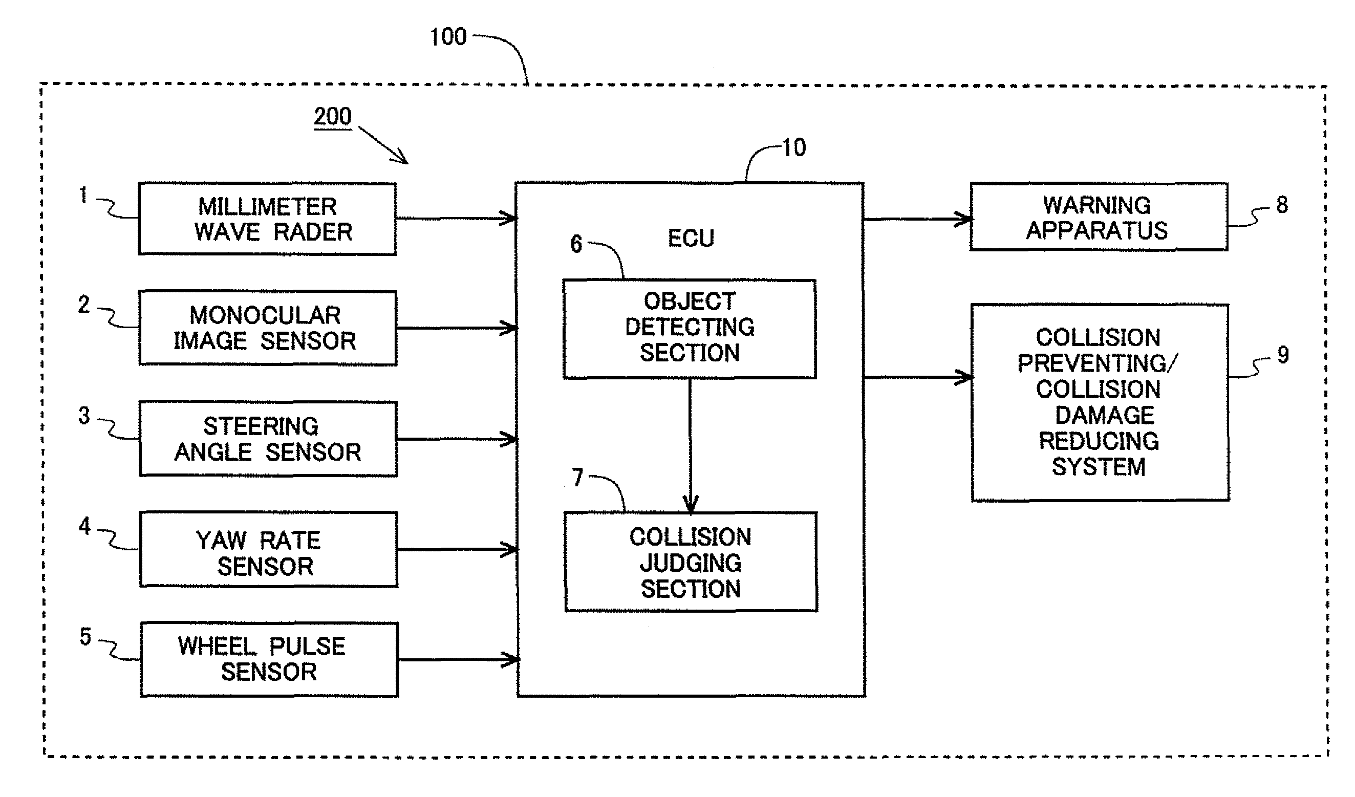
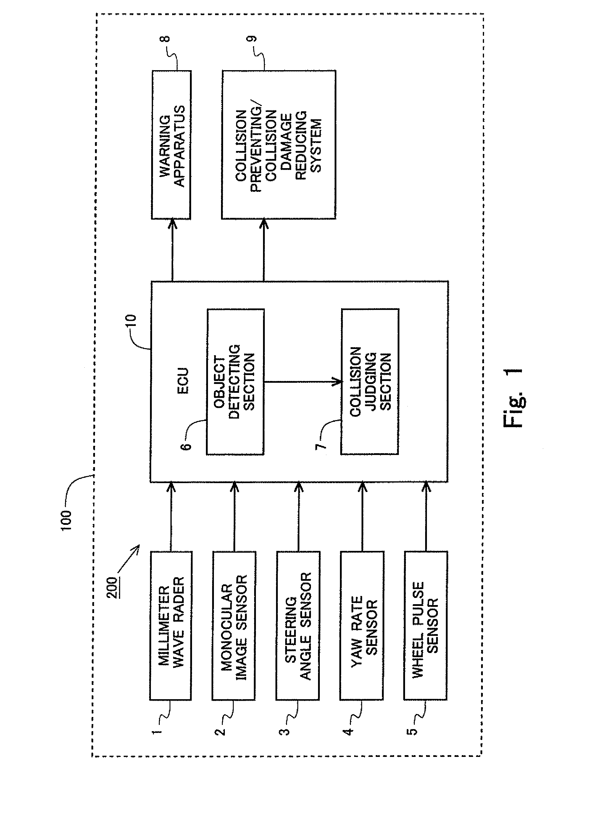
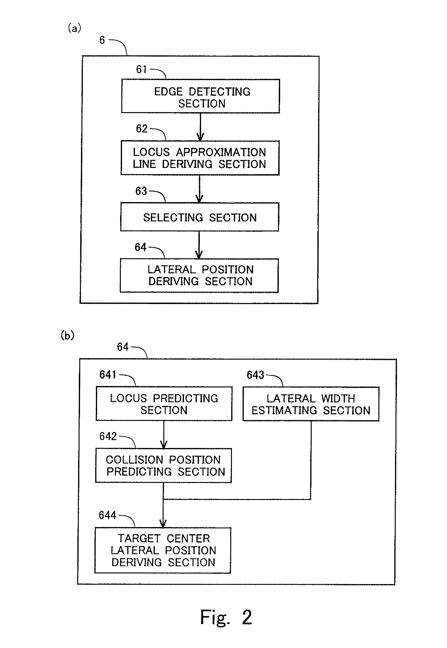
[0052]In this section, an explanation will be made about a case in which the present invention is applied to a collision predicting apparatus. FIGS. 1 and 2 show block diagrams illustrating a schematic arrangement of the collision predicting apparatus according to this embodiment. The collision predicting apparatus 200 is carried on a vehicle 100, which is an apparatus to predict the collision between a subject vehicle 100 and an obstacle including, for example, another vehicle (object vehicle) and a pedestria...


PUM


Abstract

An object of the present invention is to further improve the detection accuracy of a lateral position of a target in an object detecting apparatus for detecting an object by using a radar and a monocular image sensor. In the present invention, a target corresponding to a target recognized by the radar is extracted and a right edge and a left edge of the target are acquired from an image picked up by the monocular image sensor. Further, locus approximation lines, which are straight lines or predetermined curved lines for approximating loci of the right edge and the left edge, are derived for the both edges. The edge, which has a larger number of edges existing on the locus approximation line, is selected as a true edge of the target from the right edge and the left edge. The lateral position of the target is derived on the basis of the position of the selected edge.

Description

TECHNICAL FIELD[0001]The present invention relates to an object detecting apparatus and an object detecting method in which an object is detected on the basis of information acquired by a radar and an image sensor.BACKGROUND ART[0002]In recent years, safety systems such as PCS (Pre-crash safety system) and the like are developed in order to avoid the collision or reduce the damage caused by the collision. In order to preferably realize such a safety system, it is necessary to correctly grasp, for example, the position and the size of an obstacle including, for example, a pedestrian and a vehicle other than a subject vehicle as well as the distance between the obstacle and the subject vehicle. An object detecting apparatus, which is based on the use of a radar and a stereo image sensor, is known as a technique for grasping, for example, the position, the size, and the distance as described above.[0003]When the radar is used, it is possible to recognize a target (object provided as a ...

Claims


Application Information

Patent Timeline
Patent Type & Authority Patents(United States)
IPC IPC(8): G01S13/86G01S13/93G01S13/931
CPCG01S13/931G01S13/867G08G1/16B60R21/013B60R21/0134G01S2013/9375G01S2013/9353G08G1/166G01S2013/932G01S2013/93271
Inventor KATOH, MASAYUKI
Owner TOYOTA JIDOSHA KK
Why Eureka
Try Eureka