
Fuel filter system, especially for diesel engines

a technology for filtering systems and diesel engines, applied in the direction of filtration separation, separation processes, machines/engines, etc., to achieve the effect of efficient purification and greater operating reliability

Active Publication Date: 2013-12-24
HYDAC FILTERTECHNIK GMBH
View PDF8 Cites 2 Cited by
  • Summary
  • Abstract
  • Description
  • Claims
  • Application Information

AI Technical Summary

Benefits of technology

The invention is an improved fuel filter system that has better reliability and efficient purification. The system uses an activated carbon filter device to purify the exhaust vapor, which is pre-purified to remove diesel-oil components. By avoiding the risk of saturation and loss of purification action, the system ensures that no separated water with oil components is sent directly through the activated carbon filter. This results in a higher purification efficiency of the exhaust vapor.

Problems solved by technology

Even in the event of a failure of the control function of the release device, for example, in the case where a release valve remains permanently open or a release pump connected to the collection chamber remains continuously in operation, meaning that from the sump connected to the collection chamber an excessive amount of separated water still carrying pollutants and, potentially, diesel oil located even above the separation layer in the sump might reach the evaporator device, closing the exhaust vapor outlet prevents the environment from being polluted.

Method used


Image

  • Fuel filter system, especially for diesel engines
  • Fuel filter system, especially for diesel engines
  • Fuel filter system, especially for diesel engines

Examples


Embodiment Construction

[0020]The invention is explained below using embodiments in which the fuel filter system is part of the system for supplying a diesel engine (not shown) with diesel oil. The invention can also be used in connection with other hydrocarbon compounds that serve as fuels in which it is desirable or necessary to separate water before combustion in the engine.

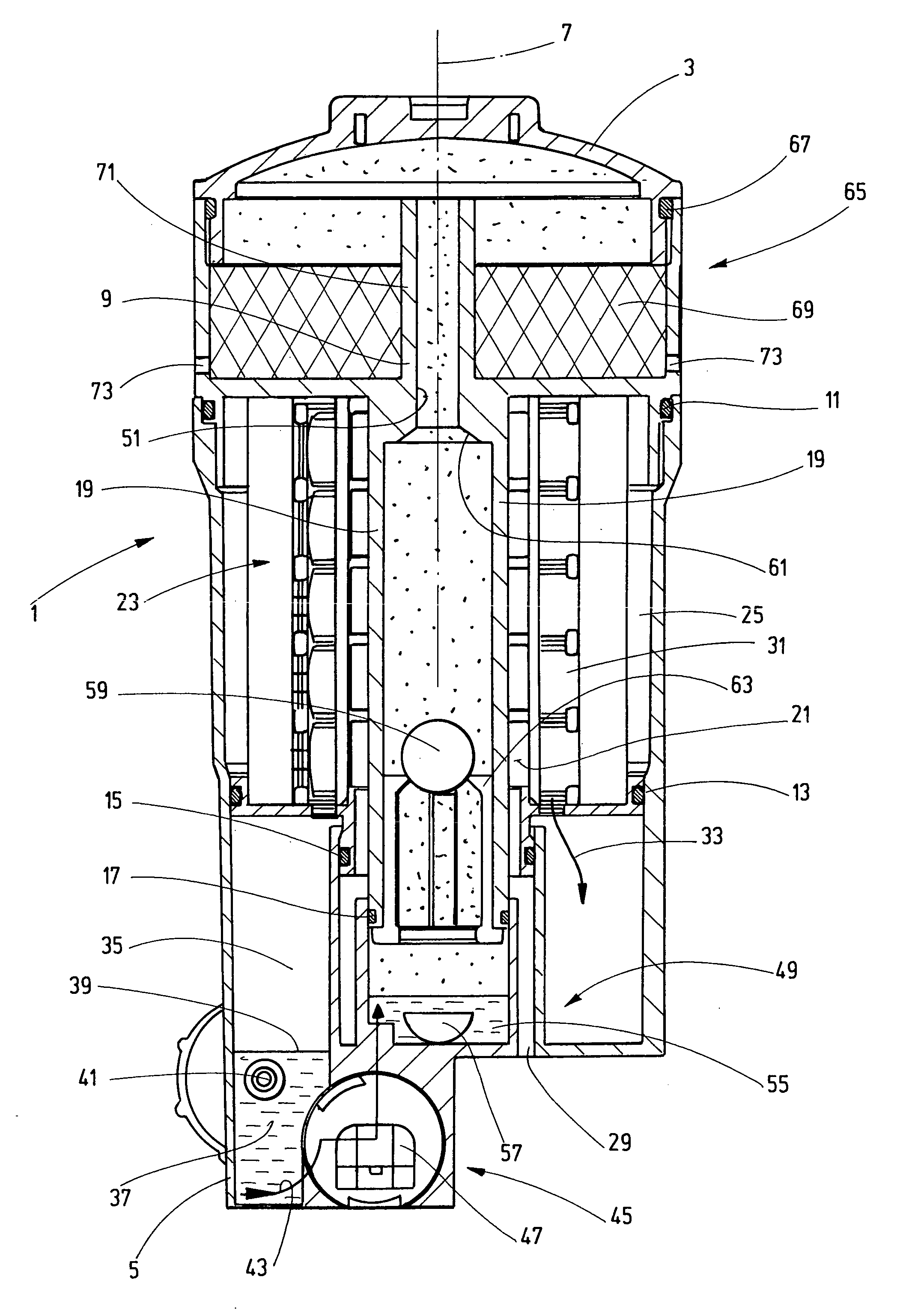
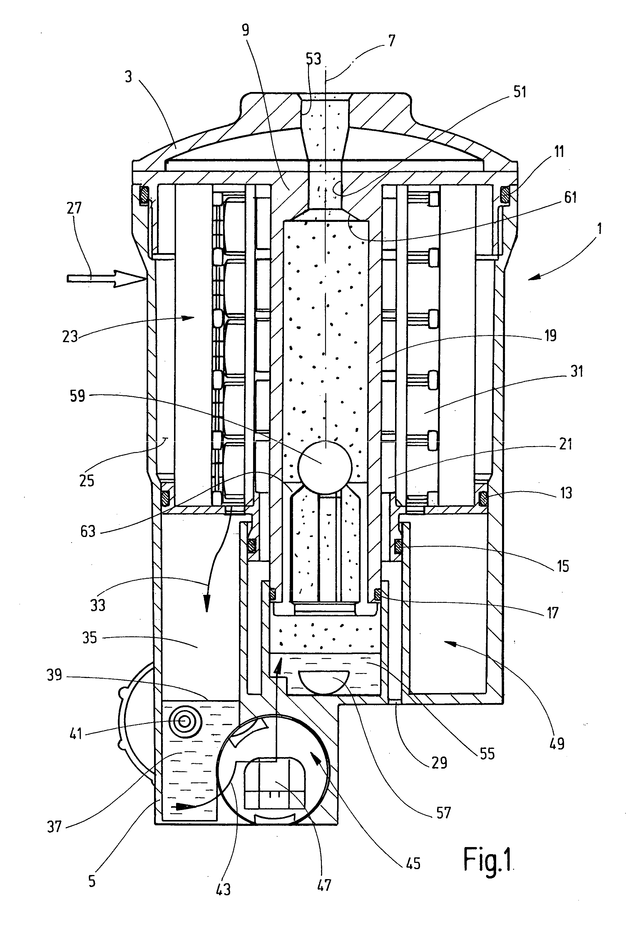
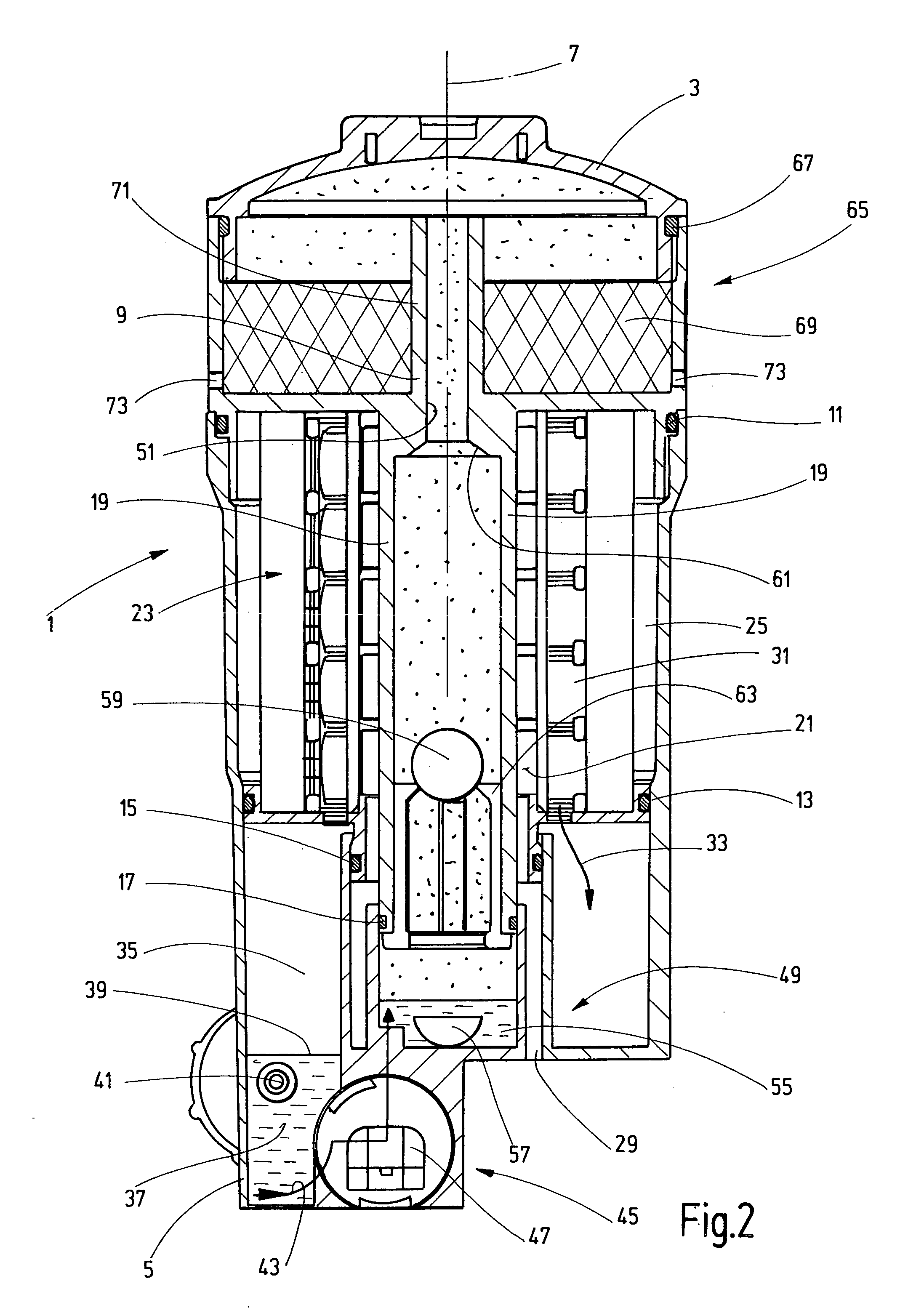
[0021]FIG. 1 shows a first embodiment with a filter housing 1 tightly sealed at the top by a removable cover 3. Aside from a bottom part 5, the housing 1 has an essentially circular-cylindrical shape with a central vertical axis 7. From the top of the housing 1, which is open when the cover 3 is removed, a coaxial inner body 9 is inserted into the housing 1. The inner body is sealed against the housing walls by sealing arrangements 11, 13, 15, and 17. With its coaxial inner pipe 19, the inner body 9 forms an evaporator housing.

[0022]The outer side of the inner pipe 19 abuts the clean side 21 of a concentric fuel filter device 23 moun...


PUM

PropertyMeasurementUnit
Levelaaaaaaaaaa

Abstract

A fuel filter system, especially for Diesel engines includes filter housing (1) having a fuel inlet (27) and a fuel outlet (29) and a dehydrating filter medium (23) between the inlet and the outlet for the fuel to pass through. The filter housing (1) has a collection chamber (35) for the water trapped by the filter medium from which collection chamber the water can be supplied to a water absorbing and evaporating device (49) via a controlled dispenser (45). The components of the evaporating steam are releasable into the environment through the evaporating steam outlet (51). The water absorbing and evaporating device (49) has a valve arrangement (59, 61) by which the evaporating water outlet (51) can be closed depending on an inadmissible amount of non-evaporated water (55) collected in the evaporating device (49).

Description

FIELD OF THE INVENTION[0001]The invention relates to a fuel filter system, especially for diesel engines, with a filter housing having a fuel inlet, a fuel outlet and a water separating filter medium through which fuel can flow and which is located between the inlet and outlet. The filter housing has a collection chamber for water separated by the filter medium. From the collection chamber, water can be fed via a controllable release device to a water absorbing and evaporating device. From the evaporating outlet of the water absorbing and evaporating device, the components of the exhaust vapor can be released into the environment.BACKGROUND OF THE INVENTION[0002]To protect the engine injection system, fuel filter systems are usually designed in such that not just impurities such as floating particulates, dust, etc., are separated, but also that water is separated and removed. Since the separated water may still be contaminated with diesel oil, it cannot be released directly into the...

Claims


Application Information

Patent Timeline
IPC IPC(8): F02M37/22B01D36/04B01D35/18
CPCB01D35/147B01D35/185B01D36/006F02M37/221F02B3/06F02M37/223F02M37/30F02M37/44F02M37/28
Inventor EBERLE, RICHARD
Owner HYDAC FILTERTECHNIK GMBH
Learn More