Touch sensor panel using dummy ground conductors

a technology of ground conductors and touch sensors, applied in the field of touch detection, can solve the problems of non-uniformity and algorithm adaptation errors, and sense elements to report erroneous signal values, so as to reduce signal interference and reduce the errors of touch detection algorithms

Active Publication Date: 2013-12-24
APPLE INC
View PDF61 Cites 18 Cited by
  • Summary
  • Abstract
  • Description
  • Claims
  • Application Information

AI Technical Summary

Benefits of technology

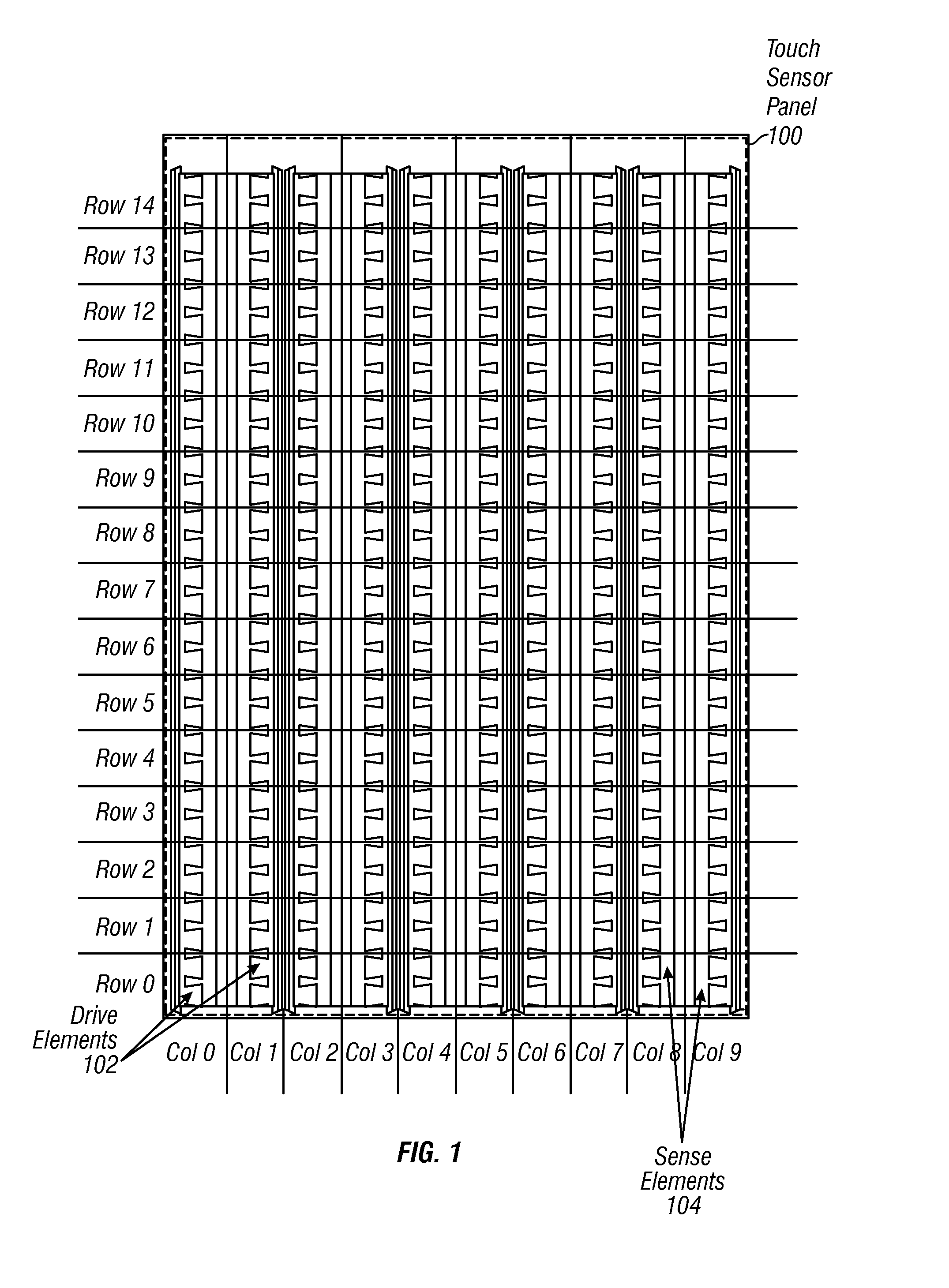
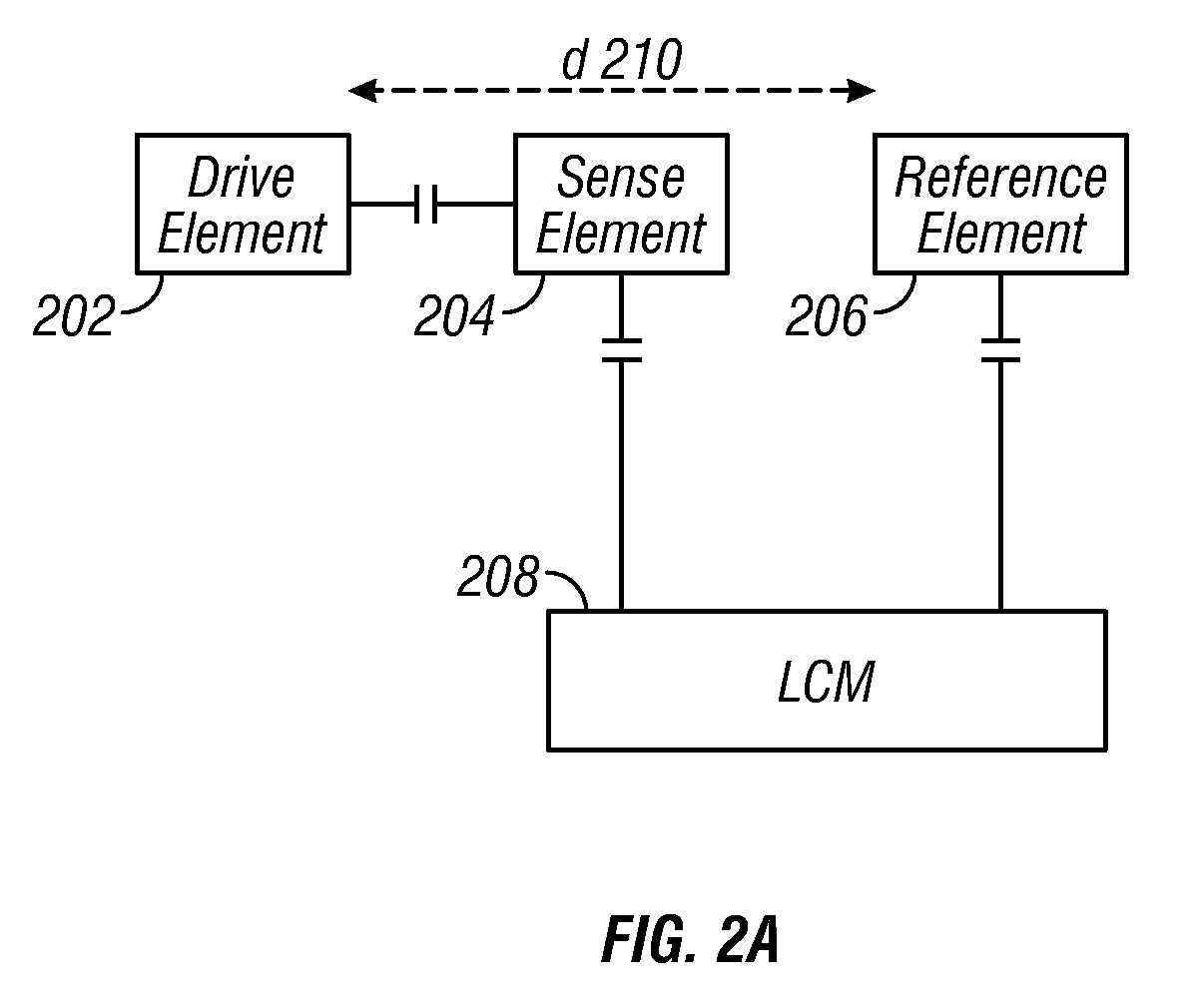
[0007]Unfortunately, electrical noise coupling from the LCM to the touch sensor electrodes can adversely affect the touch detection mechanism of the touch sensor panel, causing sense elements to report erroneous signal values. Some embodiments of the present invention therefore correct the erroneous signal values by utilizing a set of reference elements for detecting noise common to both the sense elements and the reference elements, and a correction module for effectively subtracting out the noise from the sensed values. In some embodiments, physical space on the touch sensor panel is preserved by utilizing reference elements that are a fraction of the size of the sense elements. In some embodiments, physical space on the touch sensor panel is preserved by utilizing less reference elements than sense elements.
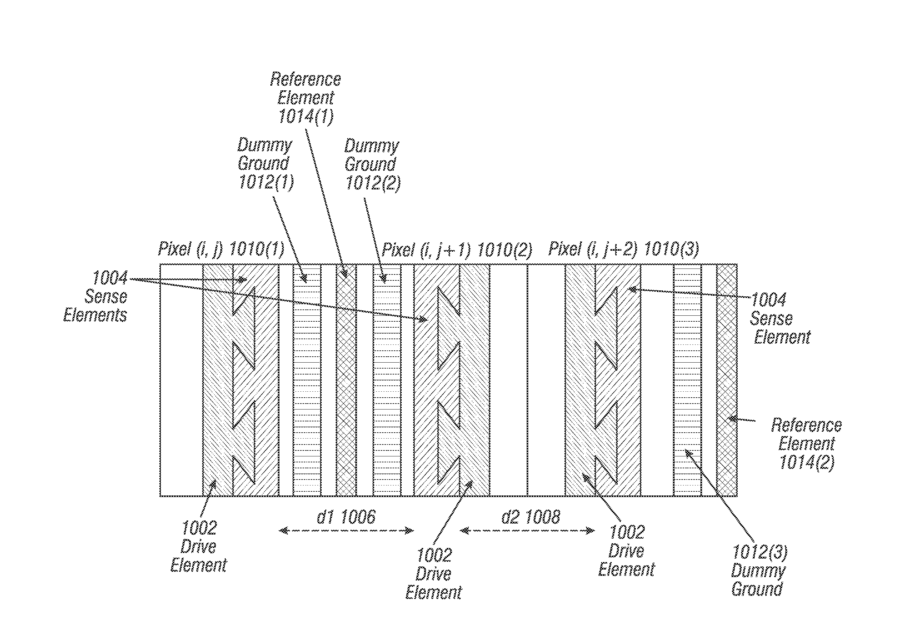
[0008]Many touch sensor panels also include sense elements that are non-evenly spaced. This non-uniformity introduces error in algorithms adapted to calculate a center of contact based upon the reported touch locations from the touch pixels. Some embodiments of the present invention therefore reduce the errors in touch detection algorithms by providing a more uniform spacing between successive sense elements. In some embodiments, one or more dummy ground elements are inserted between adjacent sense elements in order to reduce signal interference.

Problems solved by technology

Unfortunately, electrical noise coupling from the LCM to the touch sensor electrodes can adversely affect the touch detection mechanism of the touch sensor panel, causing sense elements to report erroneous signal values.
This non-uniformity introduces error in algorithms adapted to calculate a center of contact based upon the reported touch locations from the touch pixels.

Method used


Image

  • Touch sensor panel using dummy ground conductors
  • Touch sensor panel using dummy ground conductors
  • Touch sensor panel using dummy ground conductors

Examples


Embodiment Construction

[0025]In the following description of preferred embodiments, reference is made to the accompanying drawings in which it is shown by way of illustration specific embodiments in which the invention can be practiced. It is to be understood that other embodiments can be used and structural changes can be made without departing from the scope of the embodiments of this invention.

[0026]As used herein, the terms “computer program” and “software” include without limitation any sequence of human or machine cognizable steps that are adapted to be processed by a computer. Such may be rendered in any programming language or environment including, for example, C / C++, Fortran, COBOL, PASCAL, Perl, Prolog, Python, MATLAB, assembly language, scripting languages, markup languages (e.g., HTML, SGML, XML, VoXML), functional languages (e.g., APL, Erlang, Haskell, Lisp, ML, F# and Scheme), as well as object-oriented environments such as the Common Object Request Broker Architecture (CORBA), Java™ (inclu...


PUM


Abstract

Methods and apparatus for correcting electrical noise coupling from a liquid crystal module to a plurality of sense elements disposed within a touch sensor panel, and for reducing errors in touch detection algorithms. Erroneous signal values detected by the sense elements may be corrected by utilizing a set of reference elements for detecting noise common to both the sense elements and the reference elements, and a correction module for effectively subtracting out the noise from the sensed values. Errors in touch detection algorithms may be reduced by providing a more uniform spacing between successive sense elements. In some embodiments, one or more dummy ground elements may be inserted between adjacent sense elements in order to reduce signal interference.

Description

FIELD OF THE INVENTION[0001]The present invention relates generally to the field of touch detection. More particularly, the present invention is directed in one exemplary aspect to methods and apparatus for improved touch detection in touch input devices.BACKGROUND OF THE INVENTION[0002]Many types of input devices are presently available for performing operations in a computing system, such as buttons or keys, mice, trackballs, joysticks, touch sensor panels, touch screens and the like. Touch screens, in particular, are becoming increasingly popular because of their ease and versatility of operation as well as their declining price. Touch screens can include a touch sensor panel, which can be a clear panel with a touch-sensitive surface, and a display device such as a liquid crystal display (LCD) that can be positioned partially or fully behind the panel so that the touch-sensitive surface can cover at least a portion of the viewable area of the display device. Touch screens can all...

Claims


Application Information

Patent Timeline
Patent Type & Authority Patents(United States)
IPC IPC(8): G06F3/045G06F3/041G08C21/00G06F3/044G01R27/26
CPCG06F3/0418G06F3/044G06F3/04182G06F3/0443
Inventor GRUNTHANER, MARTIN PAULHOTELLING, STEVE PORTER
Owner APPLE INC
Why Eureka
Try Eureka