
Eureka
For R&D, Eureka makes reading and utilizing patents & technical documents easy.
Eureka AIR
Designed for self-driven R&D workflows. Generate viable solutions, solve complex R&D challenges, empower your innovation with AI.

Eureka Materials
Designed for material experts only. Revolutionize your material R&D, from search, analyze, to developing new materials.

TechResearch
Generate reliable direction feasibility study reports for your R&D in just a few steps.

TechSeek
Discover and master advanced knowledge NOW. Basics, ideas, possibilities, all at once.

TechMind
As an expert in R&D Theories, TechMind can generates customized viable solutions instantly.

TechRisk
Analyze your overall solution with one click, know your potential R&D risks in advance.

TechMonitor
Get weekly tech updates, stay abreast of the latest tech innovations and key insights.
Lifting device adapted to be mounted in an openable structure
- Summary
- Abstract
- Description
- Claims
- Application Information
AI Technical Summary
Benefits of technology
Problems solved by technology
Method used
Image

Examples
first embodiment
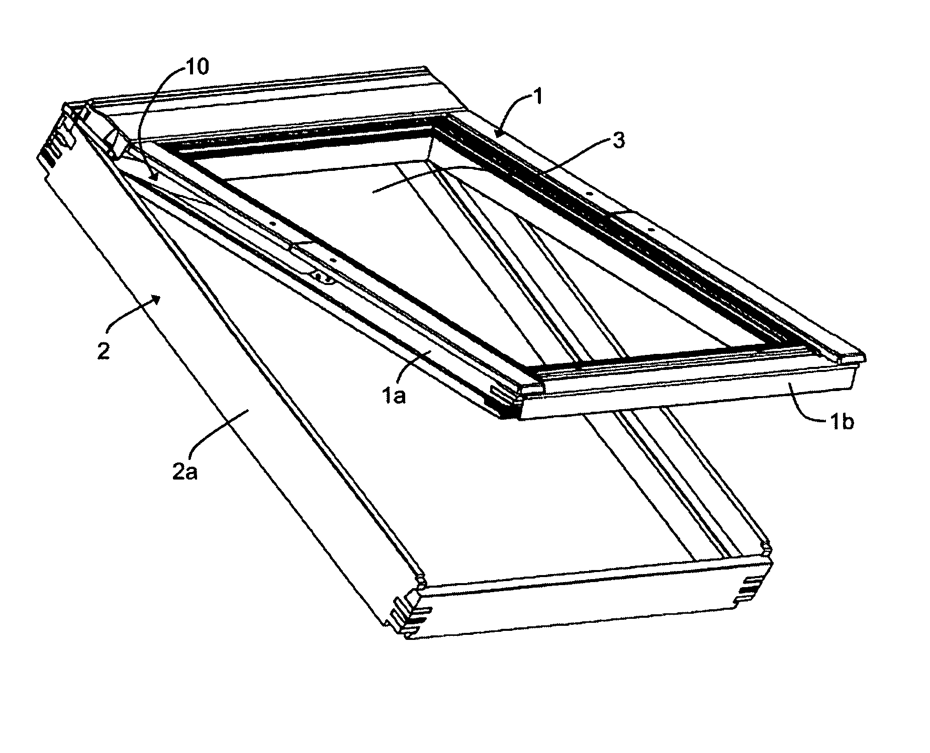
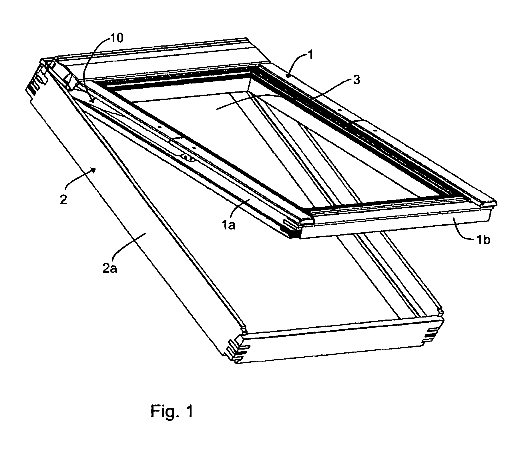
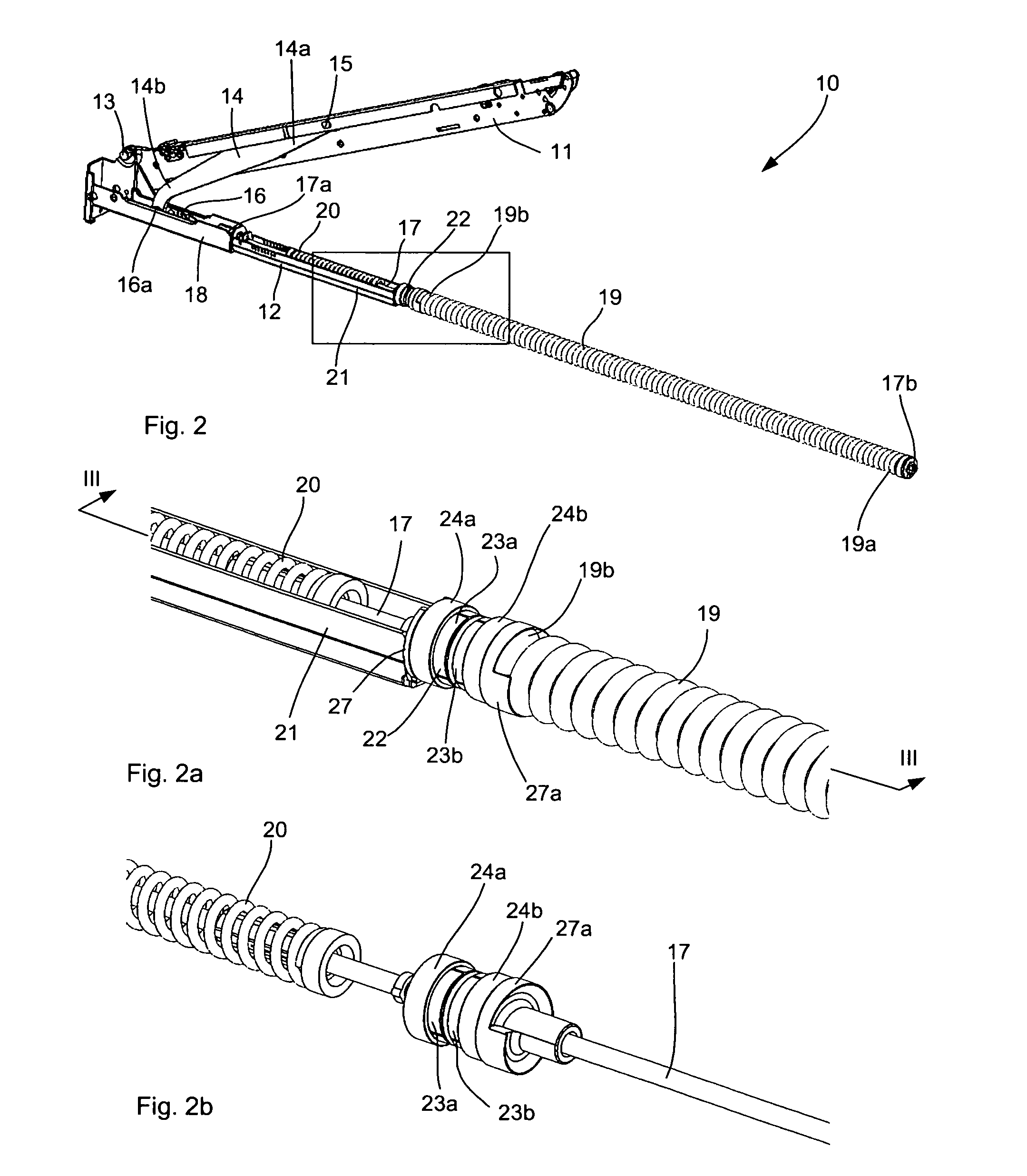
[0049]FIG. 2 shows a detailed view of the lifting device 10 of the window shown in FIG. 1, the lifting device being according to the second aspect of the present invention. The lifting device 10 comprises a first plate member 11 and a second plate member 12. The first and second plate members 11, 12 are connected with each other by means of a hinge 13. In the embodiment of the window shown in FIG. 1, the first plate member 11 is connected with the sash side member 1a, the second plate member 12 being connected with the frame side member 2a. A similar, mirror-inverted lifting device is correspondingly positioned at the opposite side members of the sash and frame. When the window is mounted in the surface (not shown), the second plate member 12 is connected with the stationary part of the structure in question, in casu the frame 2. In case the window is provided with an intermediate frame as described in the above, the connection between the intermediate frame and the glass-carrying s...
third embodiment
[0069]FIG. 5 shows a detail of a lifting device, which is according to the second aspect of the invention. A braking device 222 of this lifting device comprises a centrally positioned abutment member 224 with lateral, linearly inclining slide faces 225a, 225b, which abut respective linearly inclining slide faces 225a, 225b of respective laterally projecting brake shoes 223a, 223b. The abutment member 224 is connected to, i.e. movable with, a spring arrangement, which may comprise a main spring 19 as described above, in which case the abutment member is preferably axially fixed in relation to an end 19b of the main spring 19. The brake shoes 223a, 223b are of equal size and shape and may be connected to, i.e. axially fixed in relation to, the slide shoe 16 of the embodiments described above. The brake shoes 223a, 223b and the abutment member 224 are preferably manufactured from a plastic material such as POM9021C. Alternatively, the abutment member 224 is manufactured from steel or t...
second embodiment
[0087]The graph IV shown in FIG. 9 shows that a comparable hysteresis effect may be achieved with the braking device 122 of a lifting device according to the invention. Note that a similar adjustment of the graph inclination as between the graphs II and III of FIG. 8 could be achieved if modifying the braking device 122 to be according to the braking device 422 of FIG. 10, which is explained below.
[0088]FIG. 10 schematically shows a braking device 422 of a fifth embodiment of a lifting device, this lifting device being in accordance with the first and second aspects of the present invention. The braking device 422 is a development of the braking device 122 according to the second embodiment and shown in FIG. 4. Comparing to the braking device 122 both abutment member 424 and brake shoe 423 of this embodiment have been separated into two parts, denoted 424a, 424b and 423a, 423b, respectively; the embodiment in this respect being comparable to the fourth embodiment shown in FIGS. 6 to...
PUM
 Abstract
Description
Claims
Application Information
 - R&D Engineer
- R&D Manager
- IP Professional
- Industry Leading Data Capabilities
- Powerful AI technology
- Patent DNA Extraction
Browse by: Latest US Patents, China's latest patents, Technical Efficacy Thesaurus, Application Domain, Technology Topic, Popular Technical Reports.
© 2024 PatSnap. All rights reserved.Legal|Privacy policy|Modern Slavery Act Transparency Statement|Sitemap|About US| Contact US: help@patsnap.com