Conformal wear-resistant bearing assembly

Inactive Publication Date: 2013-12-31
LITTLE ENGINE LLC
View PDF44 Cites 16 Cited by
  • Summary
  • Abstract
  • Description
  • Claims
  • Application Information

AI Technical Summary

Benefits of technology

[0006]According to one aspect of the invention, a bearing apparatus, includes: (a) a first member comprising a rigid material and having an internal bore defining a first contact surface; (b) a second member disposed in the internal bore of the first member, the second member comprising a rigid material and having an outer cylindrical surface defining a second contact surface; (c) wherein contact surfaces are wear-resistant, and wherein the first and second members are positioned relative to each other by a plurality of protruding bearing elements contacting at least one of the first and second contact surfaces, so as to transfer mechanical loads between the first and second members, while allowing relative translation and/or rotation between the first and second members, wherein each bearing element includes a raised central portion flanked by a pair of beam portions; and (e) wherein the bearing elements are shaped and sized so as to deform elastically and conform in a regular or irregular shape to the at least one contact surface.
[0007]According to another aspect of the invention, a bearing apparatus includes: (a) an inner member comprising a rigid material and defining a first contact surface; (b) an outer member comprising a rigid ma

Problems solved by technology

Sliding bearing assemblies using two hard elements of conventional design will be, however, subject to rapid wear.
First, a bearing having one hard, rigid element on another will not be perfectly s

Method used


Image

  • Conformal wear-resistant bearing assembly
  • Conformal wear-resistant bearing assembly
  • Conformal wear-resistant bearing assembly

Examples


Embodiment Construction

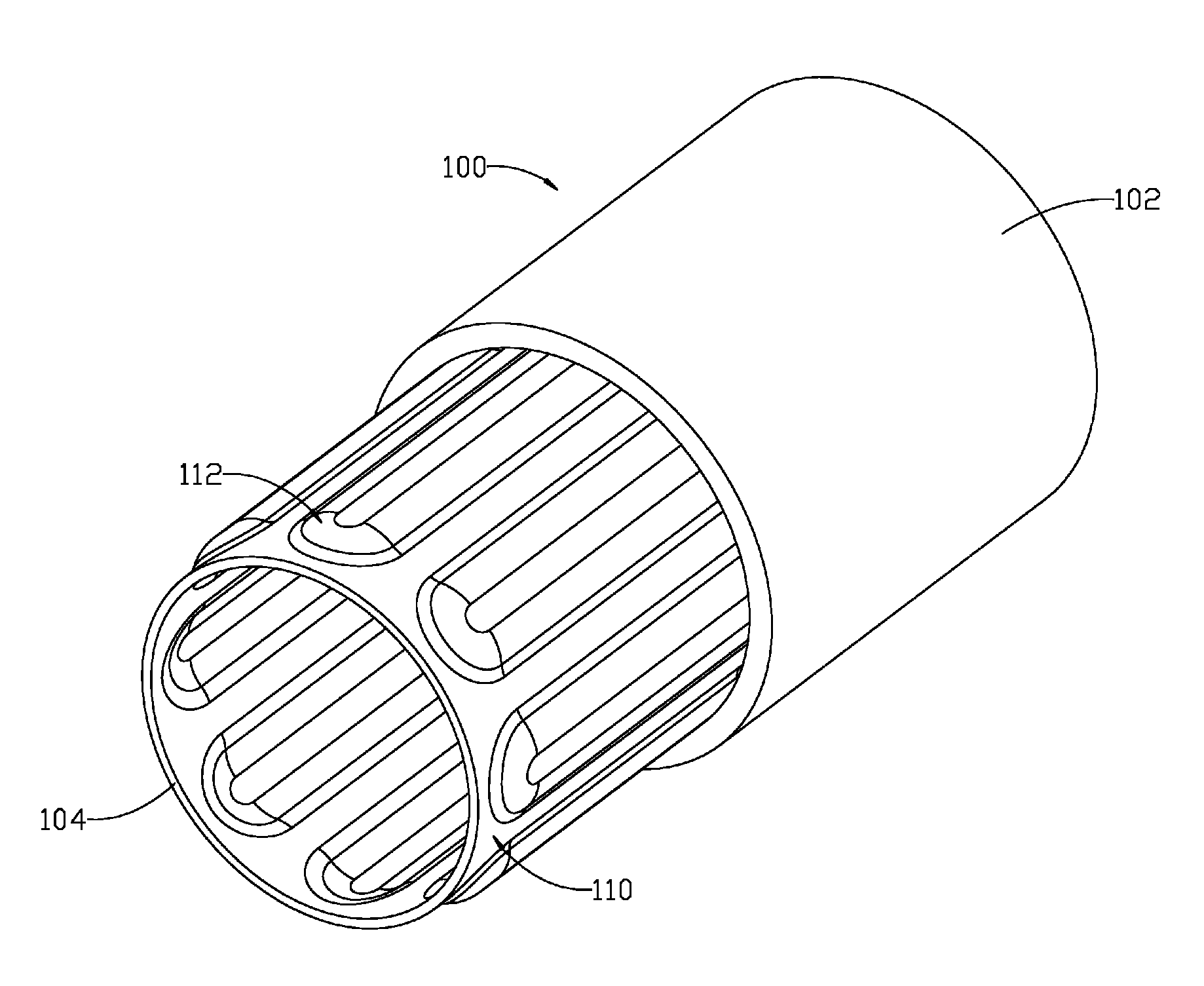
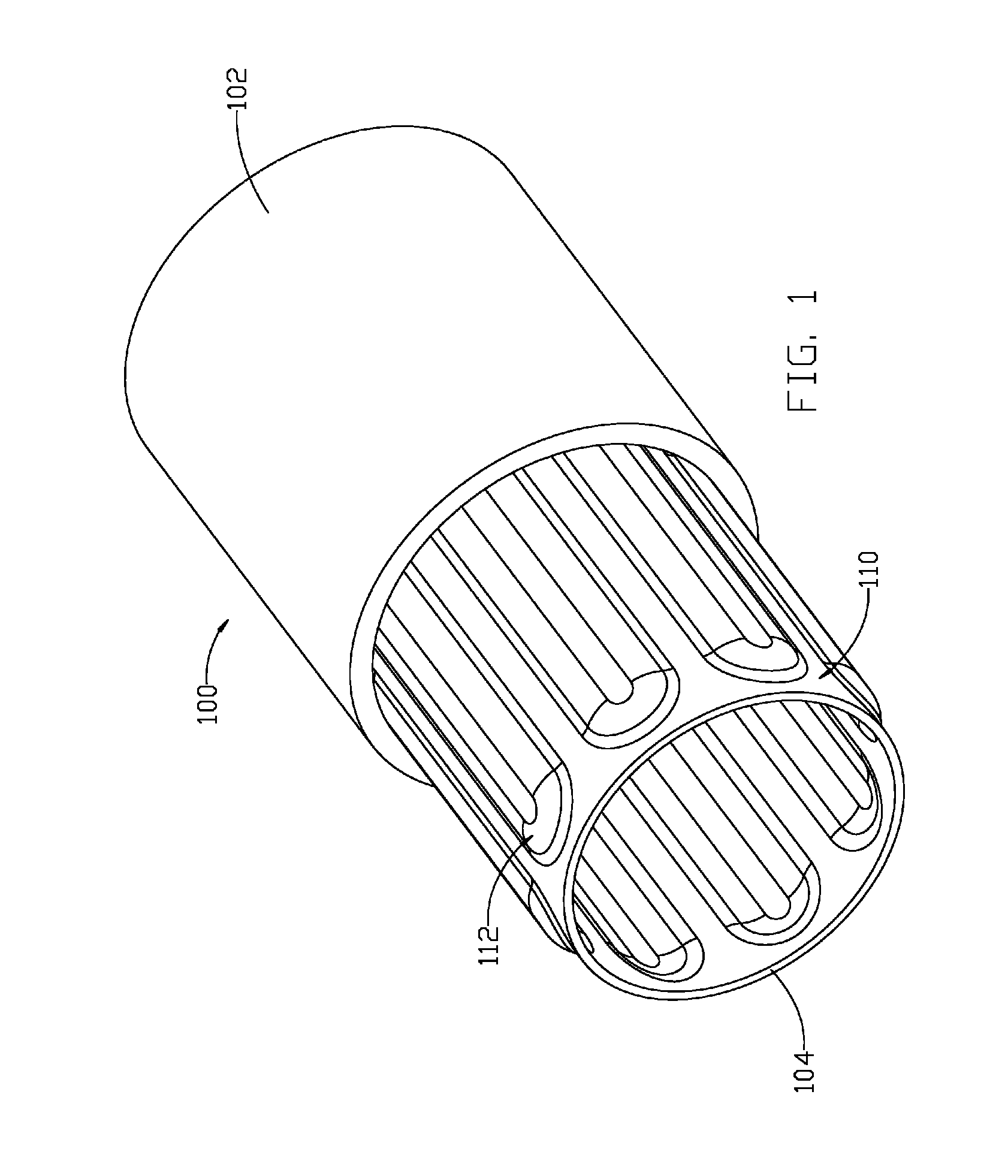
[0028]In general, the present invention is a bearing assembly for two concentric members of a machine or mechanical assembly which can move relative to each other (e.g. relative rotation or translation). As an example, the invention could be used between a bore in a housing of an industrial valve and the shaft or stem of the valve (where the valve stem can rotate and / or translate relative to the housing.) As will be explained further, the bearing may be a separate component, or parts of the bearing may be integral to one or both of the contacting members. Furthermore, the bearing described herein may be used directly between two machine elements, or the assembly described herein (using two member with a bearing between them) may be used as a self-contained bearing within a larger assembly or device.

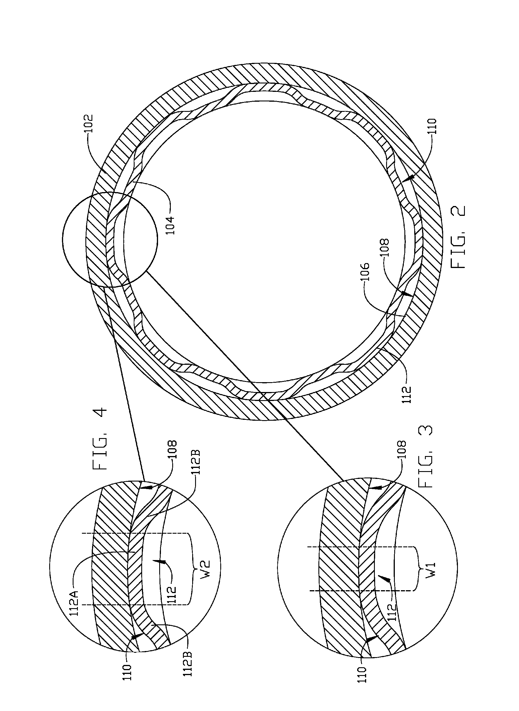
[0029]The present invention provides a unique bearing element configuration. Generally, the bearing element is flexible enough to allow elastic deformation and avoid localized load increa...


PUM


Abstract

Bearing apparatus includes: (a) a first member comprising rigid material and having a bore defining a first contact surface; (b) a second member disposed in the bore, the second member comprising rigid material and having a cylindrical surface defining a second contact surface; (c) wherein both contact surfaces are wear-resistant, and wherein the first and second members are positioned relative to each other by a plurality of protruding bearing elements contacting at least one of the first and second contact surfaces, so as to transfer mechanical loads between the members, each bearing element including a raised central portion flanked by a pair of beam portions, while allowing relative translation and/or rotation between the members; and (e) wherein the bearing elements are shaped and sized so as to deform elastically and conform in an irregular shape to the at least one contact surface.

Description

BACKGROUND OF THE INVENTION[0001]This invention relates generally to bearings, and more particularly to bearings for use between two components which move relative to each other.[0002]Numerous types of mechanical assemblies require bearings to provide low-friction contact between two components. Numerous types of bearings are known, such as plain bushings, hydrodynamic and hydrostatic bearings, and rolling element bearings.[0003]For some applications it is desirable to employ a plain bearing or bushing design using exclusively “hard” materials (e.g. metals or ceramics). These materials are suitable for harsh industrial environments including for example high temperatures or pressures, or caustic or corrosive fluids.[0004]Sliding bearing assemblies using two hard elements of conventional design will be, however, subject to rapid wear. First, a bearing having one hard, rigid element on another will not be perfectly shaped to a nominal geometry. Such imperfections will result in points...

Claims


Application Information

Patent Timeline
IPC IPC(8): F16C27/00F16C17/00
CPCF16C27/00F16C27/02F16C33/04F16C31/02F16C17/00F16C29/002F16C17/18F16C3/02F16C17/246F16D1/0835
Inventor KELLAR, FRANZ W.CROWDER, JR., HAROLD LLOYDDUQUETTE, SCOTT M.
Owner LITTLE ENGINE LLC
Why Eureka
Try Eureka