Transluminal cardiac ball valve and method for deployment thereof

a technology of transluminal and cardiac ball valve, which is applied in the field of prosthetic transluminal plunger and cage cardiac valve, can solve the problems of increased time, cost, risk, difficulty and trauma associated with percutaneous procedures, and valve may be problematic, and the valve may be problematic with regard to longitudinal stability

Inactive Publication Date: 2013-12-31
VACTRONIX SCI LLC
View PDF20 Cites 5 Cited by
  • Summary
  • Abstract
  • Description
  • Claims
  • Application Information

AI Technical Summary

Problems solved by technology

The flow-regulation mechanism includes a caged ball delivered secondary to the stent, thus requiring two catheters for delivery in addition to any initial valvuloplasty, which increases the time, costs, risks, difficulty and trauma associated with a percutaneous procedure.
Due to the flared ends, this valve may be problematic for implantation in a patient's descending aorta.
Also, the portion of the ball cage where the tines come together with the anchor funnel would be obstructive to the flow, leading to thrombosis.
Because opposite ends of the valve are connected only by the single rod, the valve may be problematic with regard to longitudinal stability.
Further, patients needing transluminal valves are typically older, debilitated, and unlikely to tolerate major surgery and a significant portion of the morbidity and mortality associated with current transluminal valve placement is related to the large diameter and low flexibility of the introducer systems.

Method used


Image

  • Transluminal cardiac ball valve and method for deployment thereof
  • Transluminal cardiac ball valve and method for deployment thereof
  • Transluminal cardiac ball valve and method for deployment thereof

Examples


Embodiment Construction

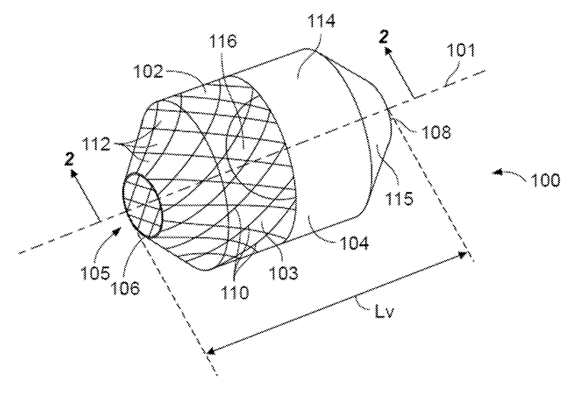
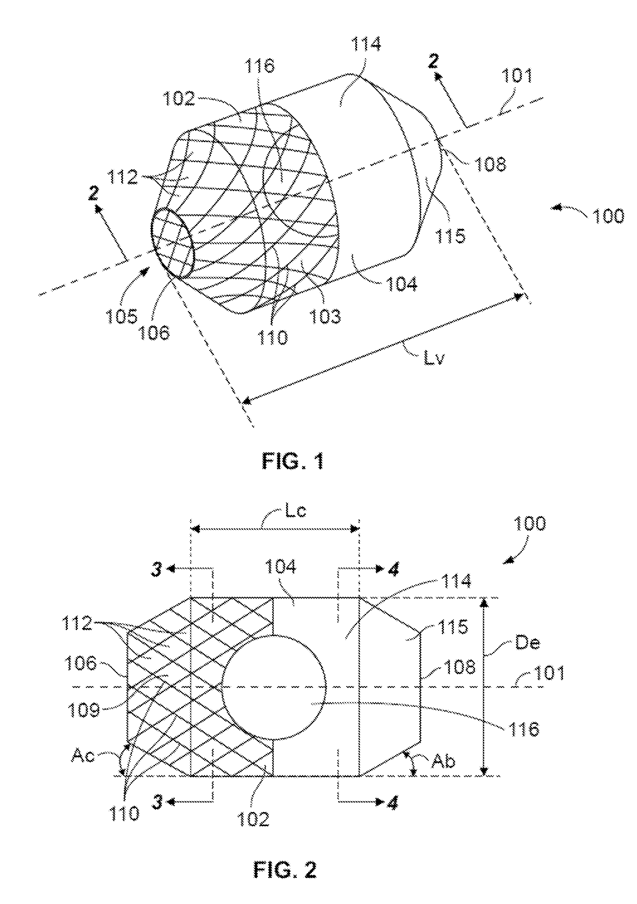
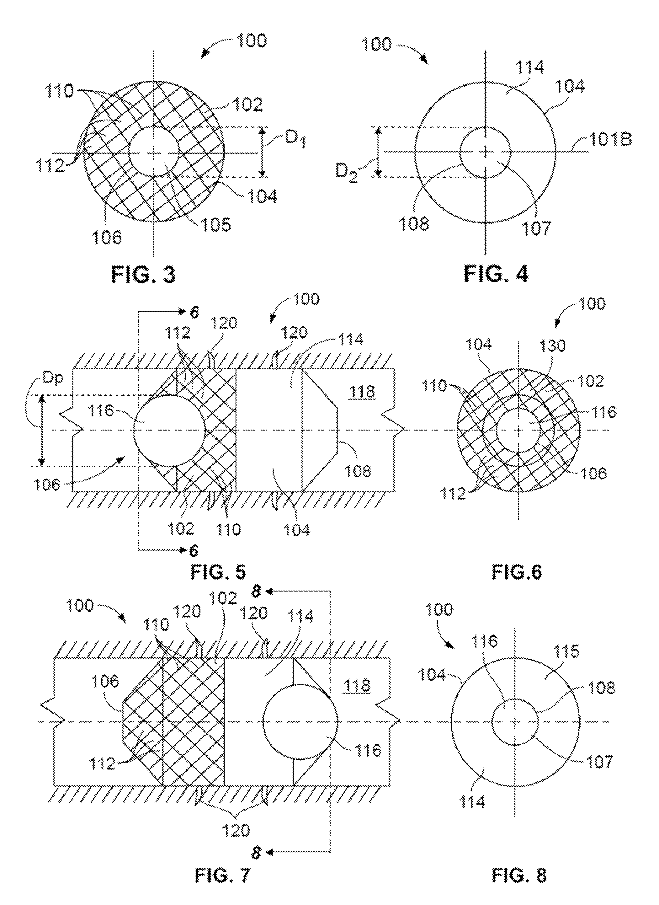
[0034]An orientational definition is provided with respect to a catheter sheath or inflation catheter as described herein, the term “proximal” is intended to mean toward the operator end of the catheter, while the term “distal” is intended to mean toward the terminal end or device-carrying end of the catheter. For purposes of this application, the term “pseudometal” or “pseudometallic” is intended to mean a biocompatible material which exhibits biological response and material characteristics substantially the same as biocompatible metals, such as for example composite materials.

[0035]In accordance with one embodiment, the plunger and / or the cage member may be made of a single material, such as stainless steel, nickel titanium alloy, cobalt-chromium alloy, or other biocompatible materials suitable for manufacture of valvular prosthetics. In accordance with an alternative embodiment, the plunger and / or the cage member may be made of at least two layers formed upon one another into a ...


PUM


Abstract

A transluminal cardiac valve includes an expandable generally tubular cage including when expanded a generally uniform central region, first and second ends each diametrically constricted relative to the central region, a blood impervious region extending from the first end of the cage to within the generally uniform central region, and an inflatable plunger freely disposed and captured within the cage when inflated.

Description

CROSS-REFERENCE TO RELATED APPLICATIONS[0001]The present application is a continuation of PCT Application Serial No. PCT / US2011 / 048121, filed Aug. 17, 2011, which claims priority to U.S. Provisional Application Ser. No. 61 / 374,558, filed Aug. 17, 2010, and claims priority to U.S. Provisional Application Ser. No. 61 / 380,093, filed Sep. 3, 2010, all incorporated by reference in their entirety herewith.BACKGROUND OF THE INVENTION[0002]The present invention relates generally to a cardiac valve suitable for implantation into mammalian subjects in need thereof. More particularly, the present invention pertains to a prosthetic transluminal plunger and cage cardiac valve that employs such plunger free to reciprocally move within a transluminal cage member under the influence of pressure differentials due to systole and diastole. It is desirable, although not essential to the present invention, that the prosthetic cardiac valve be capable of being delivered using endovascular techniques and ...

Claims


Application Information

Patent Timeline
Patent Type & Authority Patents(United States)
IPC IPC(8): A61F2/24
CPCA61F2/2424A61F2/2421A61F2/2436A61F2250/0003A61F2250/0039A61F2/2433A61F2/2418
Inventor PALMAZ, JULIO C.
Owner VACTRONIX SCI LLC
Why Eureka
Try Eureka