Linear actuator

a technology of linear actuators and actuators, applied in the direction of mechanical energy handling, dynamo-electric machines, gearing, etc., can solve the problem of lack of versatility of structures, etc., and achieve the effect of effective absorption, high accuracy, and simple structur

Active Publication Date: 2013-12-31
MINEBEAMITSUMI INC
View PDF6 Cites 6 Cited by
  • Summary
  • Abstract
  • Description
  • Claims
  • Application Information

AI Technical Summary

Benefits of technology

[0007]According to the first aspect of the present invention, the head can be made of a material that is difficult to deform, whereby reduction of positioning accuracy due to deformation of the head is prevented. On the other hand, the elastic member is made of a material that is softer than that of the head and projects from the head. Therefore, the elastic member absorbs shocks and vibrations that are transmitted between the head and a member which contacts the head.
[0008]According to a second aspect of the present invention, in the first aspect of the present invention, the elastic member projects in a direction perpendicular to the moving direction of the head. According to the second aspect of the present invention, the elastic member absorbs vibrations of the head in the axial direction by deforming, thereby preventing reduction of the positioning accuracy.
[0011]According to a fifth aspect of the present invention, according to the first aspect of the present invention, the elastic member is an O-ring, the head has a circumferential surface provided with a circumferential groove, and the O-ring is fitted into the circumferential groove. According to the fifth aspect of the present invention, shocks and vibrations that may be applied from the head to the attachment are effectively absorbed by the simple structure.
[0012]According to a sixth aspect of the present invention, according to the first aspect of the present invention, the linear driving device includes a stator unit, a rotor unit, an internal screw portion, and an external screw portion. The rotor unit is arranged and is rotatably supported in the stator unit. The internal screw portion is provided to the inside of the rotor unit. The external screw portion screws with the internal screw portion and is connected to the output shaft. The rotation movement of the rotor unit is converted into linear movement, whereby the output shaft linearly moves. According to the sixth aspect of the present invention, by using the engaging structure of the screw portions, linear drive is performed with high accuracy.

Problems solved by technology

In this case, the structure of the receiving structure must be changed, and a complex structure is required, whereby this structure lacks versatility.

Method used


Image

  • Linear actuator
  • Linear actuator

Examples


Embodiment Construction

Structure

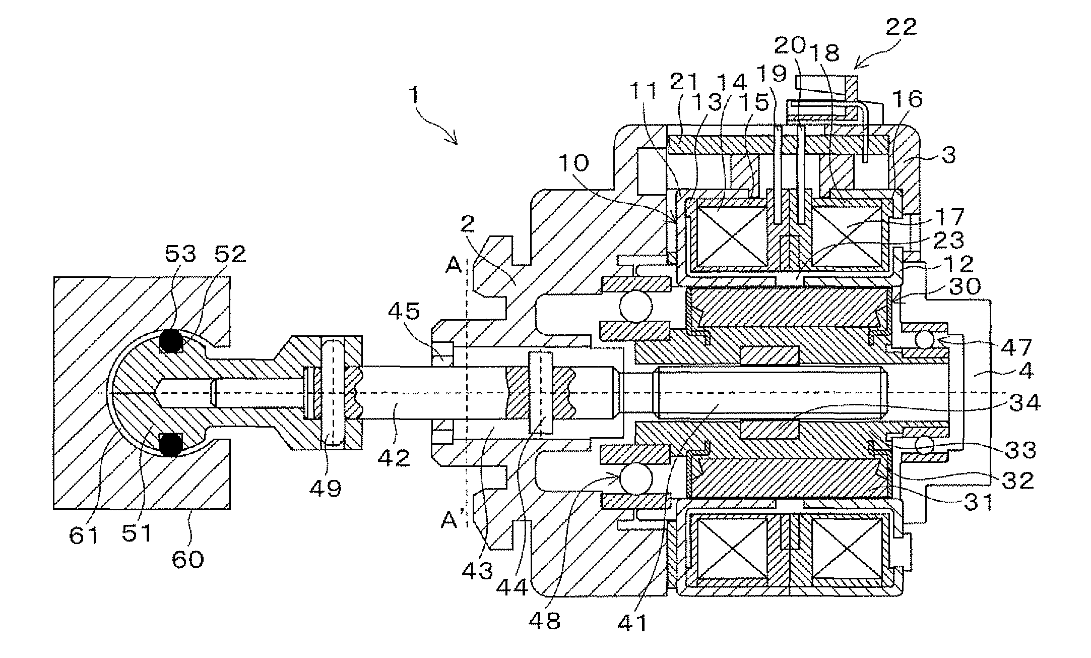
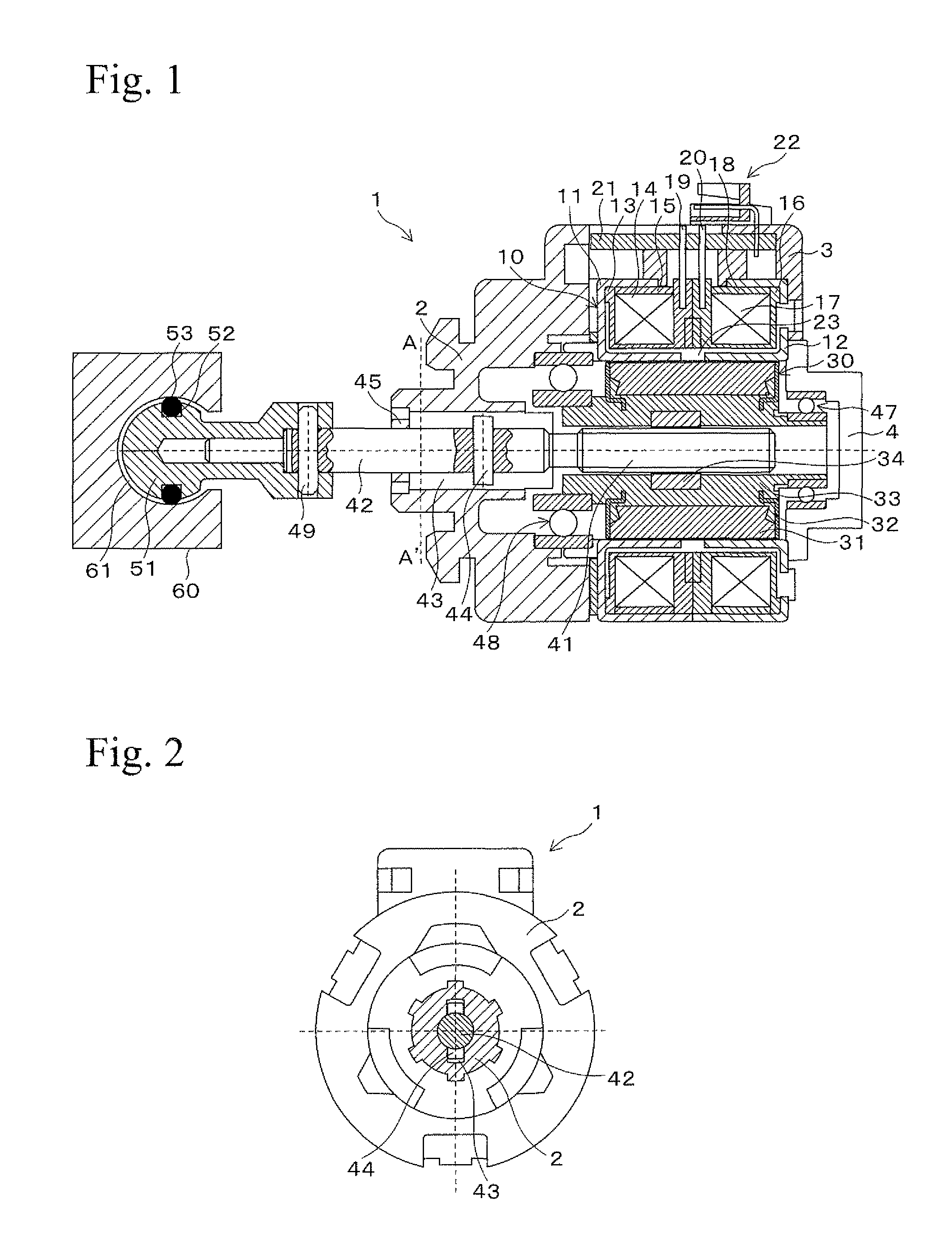
[0016]FIG. 1 shows a linear actuator 1 of an embodiment. The linear actuator 1 has a linear drive device using engagement of an external screw and an internal screw. The linear actuator 1 has a housing 2, a pin holder 3, and a stator assembly 4. The housing 2, the pin holder 3, and the stator assembly 4 are uniformly formed into an outer frame of the linear actuator 1.

[0017]The housing 2, the pin holder 3, and the stator assembly 4 are formed by mold forming (injection forming) using raw resin material. The outer frame formed of the housing 2, the pin holder 3, and the stator assembly 4 has an inside to which a stator unit 10 is fixed. The stator unit 10 has an approximately tubular shape and rotatably contains a rotor unit 30, which will be described later. The stator unit 10 is formed of a stator yoke 11, stator yoke 12, a bobbin 13, a coil (field coil) 14, a coil cover 15, a bobbin 16, a coil (field coil) 17, and a coil cover 18.

[0018]The stator yokes 11 and 12 are stato...


PUM


Abstract

A head of an output shaft of a linear actuator is modified so as to absorb vibrations that may be transmitted between the output shaft and a moving object. A linear actuator has an output shaft with a leading end to which a head is fixed. The head has an O-ring that is fitted thereto, and a part of the O-ring outwardly projects from the head. The O-ring is made of rubber that is softer than the material of the head. The head is contained in a containing space in an attachment, and in this condition, the O-ring contacts an inner circumferential surface of the containing space by deforming.

Description

BACKGROUND OF THE INVENTION[0001]1. Field of the Invention[0002]The present invention relates to a linear actuator having a specific structure in a head portion of an output shaft.[0003]2. Description of Related Art[0004]For example, a structure for moving a reflector of a vehicular lighting device is disclosed in Japanese Unexamined Patent Application Laid-open No. 2007-42288. In this structure, a vibration-absorbing function is provided to a portion of a clip to which a head portion of an output shaft of a linear actuator is connected.SUMMARY OF THE INVENTION[0005]In the structure disclosed in Japanese Unexamined Patent Application Laid-open No. 2007-42288, the vibration-absorbing function is provided by modifying a receiving structure which receives the output shaft of the linear actuator. In this case, the structure of the receiving structure must be changed, and a complex structure is required, whereby this structure lacks versatility. In view of these circumstances, it is an o...

Claims


Application Information

Patent Timeline
Patent Type & Authority Patents(United States)
IPC IPC(8): H02K41/02
CPCF16H2025/2078F16H25/20F16H2025/2037H02K7/06
Inventor MURAMATSU, KAZUOSUZUKI, KATSUTOSHI
Owner MINEBEAMITSUMI INC
Why Eureka
Try Eureka