Method of, and apparatus for the dispensing of decontaminants and fire suppressant foam

a technology of decontaminant foam and dispensing equipment, which is applied in the field of chemical, biological, radiological and nuclear decontaminant foam dispensing equipment, can solve the problems of limited ability of one military or civil service to work jointly with another, large-scale decontaminant dispensing systems that are not designed with the capability of discharging fire suppressant foam, and limited the ability of one military or civil service to work together

Inactive Publication Date: 2014-01-07
MED ENG HLDG ULC
View PDF4 Cites 3 Cited by
  • Summary
  • Abstract
  • Description
  • Claims
  • Application Information

AI Technical Summary

Benefits of technology

[0007]The present invention provides for the following four improvements in conventional CBRN dispensing equipment: 1) the dispensing of most commercial aqueous decontaminants; 2) a much larger area of coverage while maintaining a foot print equal to or less than conventional equipment; 3) the ability to dispense fire suppressant foam on a continual basis in areas unattainable to presently employed equipment; and 4) the capability of continuous radiological particle removal.
[0009]Additionally, a larger area of coverage while maintaining or reducing the foot print of the dispensing equipment is accomplished by mixing the two liquid tanks close to saturation and running free water through the system from a hydrant, pump truck or portable pump.
[0010]Another advantage is the ability to dispense fire suppressant foam on a continual basis in areas unattainable to presently employed equipment. This is made possible by the light weight and relatively small footprint of the system. This invention has a dry weight of approximately 317 Kg (700 lbs.) and a charged weight of approximately 1225 Kg (2700 lbs.) with a foot print of 1.22 m (4 ft.)×2.44 m (8 ft.). The light weight and small foot print allows the system to be transported in the box of a regular sized pick up truck or to be placed on wheels making it mobile for use within the interior of large buildings such as airports and malls.
[0011]Still another advantage is the capability of continuous radiological particle removal. This is made possible by the fact that this invention was designed with separate chemical tanks evacuated by separate pumps having their own set of controls. This allows the operating speed of each pump to be increased or decreased depending on the requirements of the operation. Another factor making this operation possible is the system size and its potential mobility.

Problems solved by technology

Decontaminant dispensing equipment was formerly developed solely for the dispensing of a particular decontaminant, rather than multiple different decontaminants, a fact which severely limited the ability of one military or civil service to work jointly with another, due to issues of incompatibility.
For example, large scale decontaminant dispensing systems were not designed with the capability of discharging fire suppressant foams.
The area coverage of CBRN decontaminant dispensing equipment—i.e., the area to which CBRN decontaminants or fire-suppressants could be effectively deployed by particular pieces of equipment—has also been limited by the size (more particularly the surface area, or “foot print” effectively occupied by such equipment) of the mechanical device.
This was mainly due to the large capacity of liquid required when using the dispensing units.
The mere size and weight of these vehicles inhibits their ability to access many locations which may require their employment.
The limited versatility of prior art devices meant that, for example, removal of radiological particles could be interrupted as systems were shut down to be recharged with the particular decontamination solutions used to trap and pull these particles from where they rested.
This increased the chance of these particles being transported to other locations downwind of the contaminated site, and also increased the time required to perform the operation.

Method used


Image

  • Method of, and apparatus for the dispensing of decontaminants and fire suppressant foam
  • Method of, and apparatus for the dispensing of decontaminants and fire suppressant foam
  • Method of, and apparatus for the dispensing of decontaminants and fire suppressant foam

Examples


Embodiment Construction

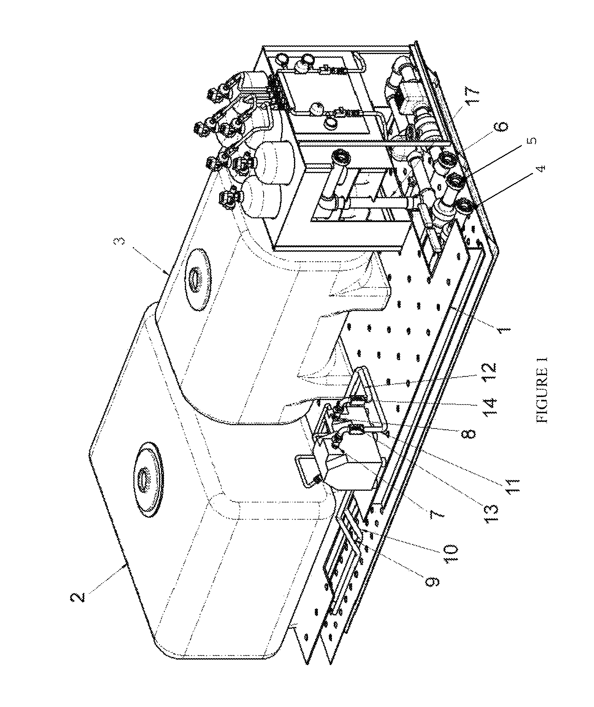
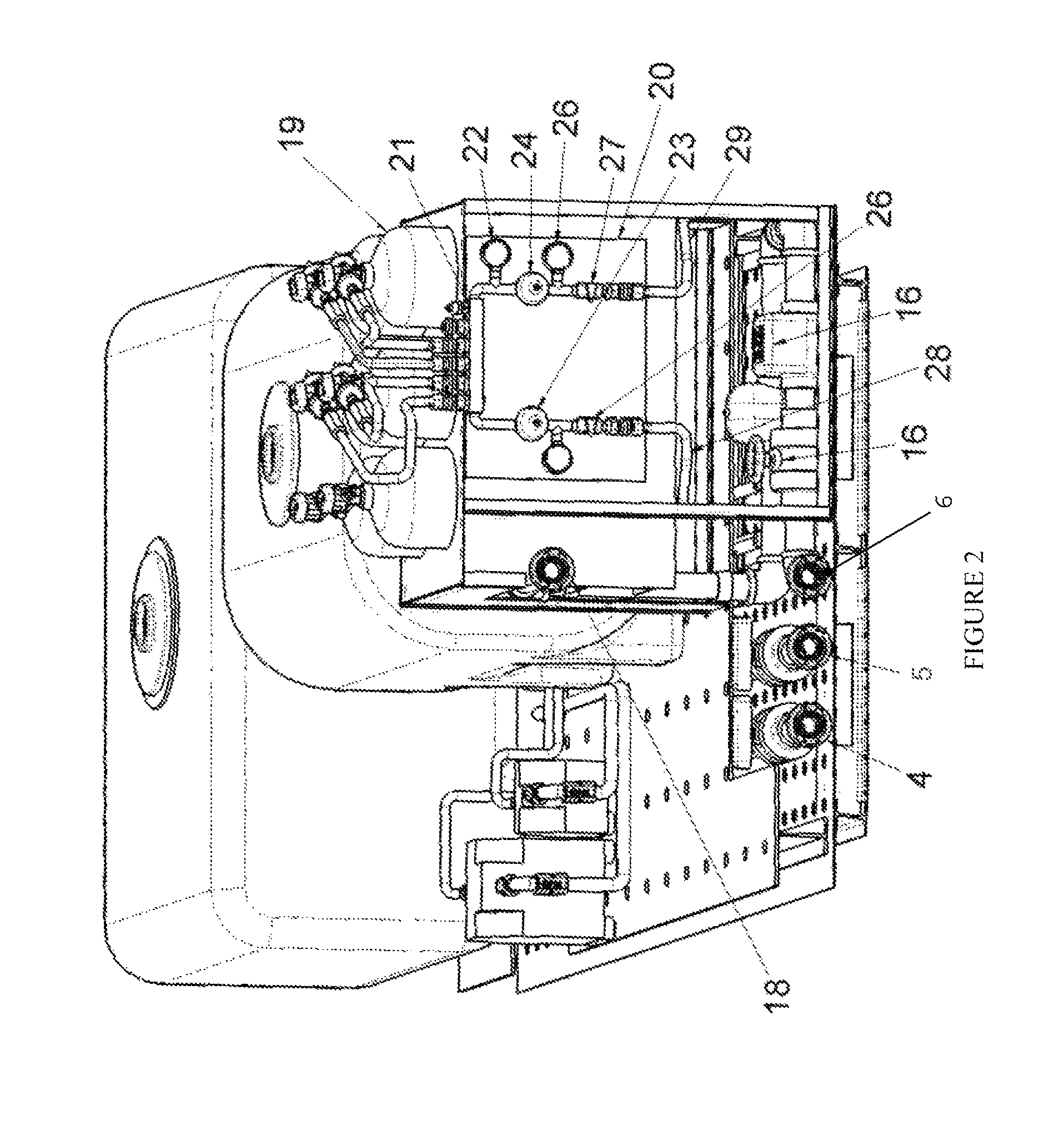
[0018]An exemplary apparatus for implementing the invention will be described with respect to the embodiments appearing in FIGS. 1-5. A partial parts list of the components used in these embodiments is summarized in the following list:

[0019]

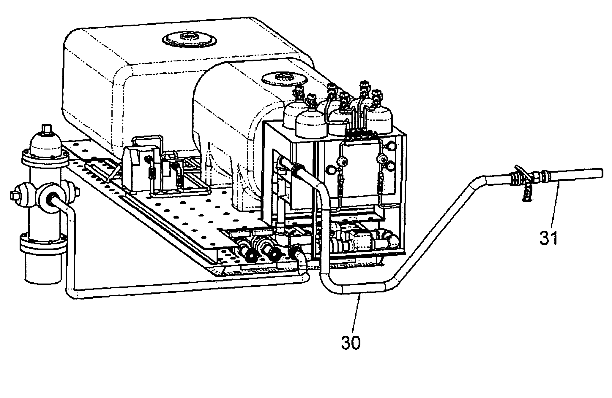
Decontaminant Dispenser Materials ListITEMDESCRIPTION1PALLET2TANK “A”3TANK “B”4FILL PIPE “A”5FILL PIPE “B”6INLET LINE7PUMP “A”8PUMP “B”9SUCTION HOSE “A”10SUCTION HOSE “B”11DISCHARGE HOSE “A”12DISCHARGE HOSE “B”13FLOW METER-DISCHARGE HOSE “A”14FLOW METER-DISCHARGE HOSE “B”15FLOW CONTROL VALVE16FLOW METER17STATIC MIXER18OUTLET LINE19AIR CYLINDER20CONTROL PANEL21MANIFOLD22AIR PRESSURE GAUGE-FIRST STAGE23PRESSURE REGULATOR-AIR LINE “A”24PRESSURE REGULATOR-AIR LINE “B”25AIR PRESSURE GAUGE SECOND STAGE26SHUT OFF VALVE-AIR LINE “A”27SHUT OFF VALVE-AIR LINE “B”28AIR LINE “A”29AIR LINE “B”301½″ HOSE31NOZZLE

[0020]Referring to FIGS. 1-4, in the event of a chemical or biological decontamination requirement the decontaminant dispenser would be prepared for op...


PUM


Abstract

This invention comprises a method of dispensing water-based decontaminants from a dispenser, comprising the steps of: (a) filling one or more tanks each with respective solutions of chemicals and water; (b) pumping the solutions from the tanks in respective hoses, each of the tanks being evacuated under the urging of a respective pump; (c) mixing the solutions at a static mixer after evacuation of the solutions from the tanks to form a mixture; (d) adding water to the mixture at the static mixer; and (e) dispensing the water-added mixture onto an incident site.

Description

FIELD OF INVENTION[0001]The present invention relates to the field of CBRN (Chemical, Biological, Radiological, and Nuclear) decontamination and fire depressant foam dispensing equipment, and more particularly, to neutralizing chemical and biological threats and to the removal of radiological particles.BACKGROUND OF THE INVENTION[0002]Decontaminant dispensing equipment was formerly developed solely for the dispensing of a particular decontaminant, rather than multiple different decontaminants, a fact which severely limited the ability of one military or civil service to work jointly with another, due to issues of incompatibility. For example, large scale decontaminant dispensing systems were not designed with the capability of discharging fire suppressant foams.[0003]The area coverage of CBRN decontaminant dispensing equipment—i.e., the area to which CBRN decontaminants or fire-suppressants could be effectively deployed by particular pieces of equipment—has also been limited by the ...

Claims


Application Information

Patent Timeline
Patent Type & Authority Patents(United States)
IPC IPC(8): A62C35/00A62C2/00A62C3/00
CPCA62C5/02
Inventor DAVIS, JOHNSORAK, DRAGAN
Owner MED ENG HLDG ULC
Why Eureka
Try Eureka