Slurry pump having impeller flow elements and a flow directing device

a technology of flow elements and directing devices, which is applied in the direction of wind motors with parallel air flow, wind motors with perpendicular air flow, liquid fuel engine components, etc., can solve the problems of affecting the flow of slurry

Active Publication Date: 2014-01-07
WEIR MINERALS AUSTRALIA LTD
View PDF33 Cites 17 Cited by
  • Summary
  • Abstract
  • Description
  • Claims
  • Application Information

AI Technical Summary

Benefits of technology

[0014]During use of such an impeller, when the impeller is caused to rotate the inducer elements can assist the uplift of particulate matter into the region of the pumping vanes and thus the subsequent removal of the matter from adjacent the impeller inlet opening. In situations such as clearing settled solids from a sump pit, the particles may be relatively large in size or naturally heavy or dense, and the inducer elements can assist with the removal of such settled material.
[0036]In response to the in use rotation of the adjacent impeller, the flow distribution vane(s) in the pump casing can assist with the efficient delivery of slurry material into the pumping chamber, where the pumping action draws the fluidised slurry material into the impeller for removal. The vane(s) can reduce swirl and improve the efficiency of delivery of the slurry flow to the in use outer surface of the back shroud of the impeller.

Problems solved by technology

This mixture is commonly referred to as slurry and because it contains solids it can be very abrasive.
Over time these particles build-up and can block the sump, particularly if the particles tend to bind together.
Such particulates can jam the rotation of the impeller and possibly damage the impeller, leading to an early failure of the sump pump.
However the impeller can still become damaged by a build-up of finer particulates within the casing.
However the effectiveness of known agitators can vary considerably and, because agitators tend to wear rapidly, their efficiency can be rapidly diminished during use.
While this may prevent jamming the rotation of the impeller, this may also limit the flow that can be pumped, which in turn may result in sump overflow.

Method used


Image

  • Slurry pump having impeller flow elements and a flow directing device
  • Slurry pump having impeller flow elements and a flow directing device
  • Slurry pump having impeller flow elements and a flow directing device

Examples


Embodiment Construction

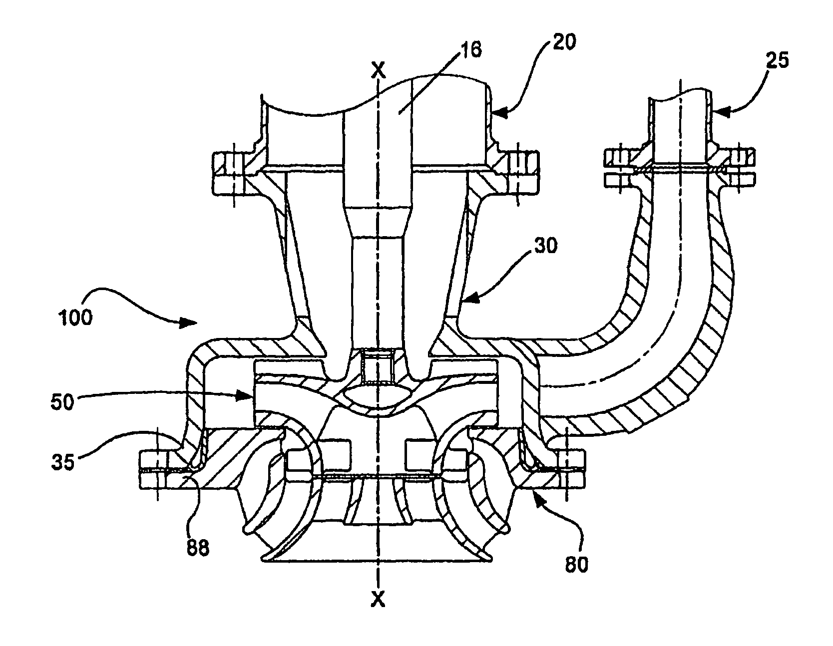
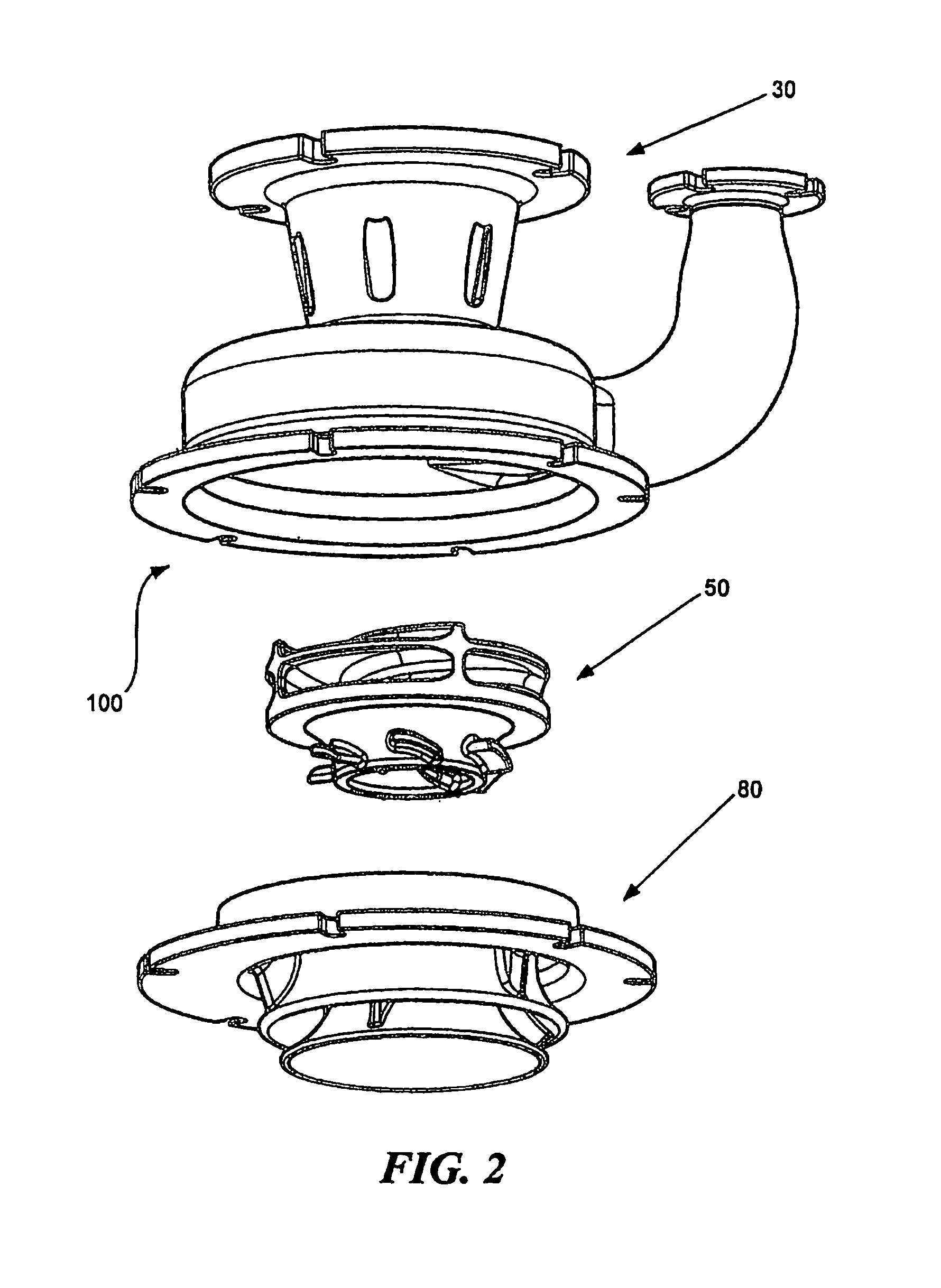
[0090]Referring now to the drawings, in FIG. 2 a pump assembly 100 is shown which comprises a pump casing 30, an impeller 50 and a flow directing device 80. The impeller 50 is disposed within the pump casing 30 and the flow directing device 80 mounted to the pump casing to enclose the impeller 50 therebetween when the three components are assembled together. In one normal mode of operation the impeller 50 is mounted for rotation about a substantially vertical axis, and the flow directing device 80 is disposed below the pump casing 30.

[0091]As shown in FIGS. 3 to 8 the pump casing 30 includes a pump body section 32 having a pumping chamber 36 therein which is adapted to receive the impeller 50. The pump body section 32 includes a peripheral side wall 34, a back wall 38 and an open front side 42. A peripheral mounting flange 35 surrounds the open front side 42. The central axis of flange 35 is axially offset with respect to the central axis of second inlet 44. The open front side 42 p...


PUM

PropertyMeasurementUnit
rotationaaaaaaaaaa
rotation axisaaaaaaaaaa
aerofoil shapeaaaaaaaaaa

Abstract

A pump assembly and components therefor including an impeller which has flow inducer elements on an inner surface of a front shroud thereof, a flow directing device or strainer having passageways for delivering material to the impeller and at least one flow circulating passageway and a pump casing having an intake section with flow distribution vanes in the region of a feed opening adjacent the intake section.

Description

TECHNICAL FIELD[0001]This invention relates generally to pumps and more particularly to pumps of the type which include for example sump pumps, submersible pumps, jet pumps and the like.BACKGROUND ART[0002]Centrifugal sump pumps find application in a wide range of industries including mining. Mining applications for sump pumps typically include pumping a mixture of water with mineral particles of different particle sizes and densities. This mixture is commonly referred to as slurry and because it contains solids it can be very abrasive. Consequently sump pumps used in mining in most instances are constructed from wear resistant materials.[0003]Sump pumps used in mining applications are typically mounted on beams on top of a usually wide and relative shallow sump or pit. A driving motor and pump bearings are all disposed above floor level so they are not submerged thereby ensuring longer life of these parts. The pumping elements are attached to a vertical shaft and are normally posit...

Claims


Application Information

Patent Timeline
Patent Type & Authority Patents(United States)
IPC IPC(8): F04D29/02F04D29/44F04D29/40B01F23/00B01F27/91
CPCF04D29/448F04D7/045B01F2003/0028F04D29/708F04D7/04F04D29/2216F04D29/24F04D13/08B23P6/00F04D29/4273F04D29/2288F04D29/2238B01F7/22Y10T29/49238F04D29/2222F04D29/426F04D29/445F04D29/628F05D2250/51F04D13/12B01F23/023B01F27/91F04D29/4293
Inventor BURGESS, KEVIN EDWARDCANTRILL, GARTH NORMAN
Owner WEIR MINERALS AUSTRALIA LTD
Why Eureka
Try Eureka