Steam turbine and methods of assembling the same

Active Publication Date: 2015-07-02
GENERAL ELECTRIC CO
View PDF6 Cites 5 Cited by
  • Summary
  • Abstract
  • Description
  • Claims
  • Application Information

AI Technical Summary

Benefits of technology

This patent describes a steam turbine that includes a seal assembly with multiple seals and an anti-swirl device to reduce swirl of cooling steam flow. The technical effect of this invention is an improved performance and efficiency of the steam turbine due to improved steam flow control and reduced pressure drop. The rotor assembly has a rotor wheelspace and a plurality of blades located within the stator. The seal assembly is coupled to the housing with the plurality of seals that define a second flow path that is in flow communication with the rotor and discharges a second steam flow toward the rotor wheelspace. The anti-swirl device reduces swirl of the cooling steam flow and improves the performance and efficiency of the steam turbine.

Problems solved by technology

In general, during operation, steam flows over and around the turbine blade, which are subject to high thermal stresses.
These high thermal stresses may limit the service life of the turbine blades, the wheel, and / or the rotor.
More particularly, as steam temperatures increase, the rotor materials may experience creep and rupture.
However, these materials may increase the cost of fabrication of the turbine rotor.
Typical cooling steam, however, may have a swirl effect that may affect the heat transfer from the rotor and / or negatively affect rotor operation.

Method used


Image

  • Steam turbine and methods of assembling the same
  • Steam turbine and methods of assembling the same
  • Steam turbine and methods of assembling the same

Examples


Embodiment Construction

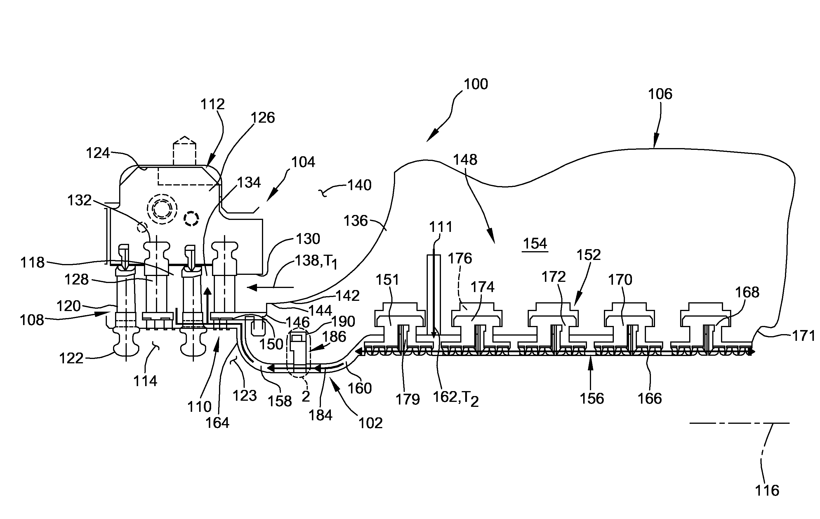
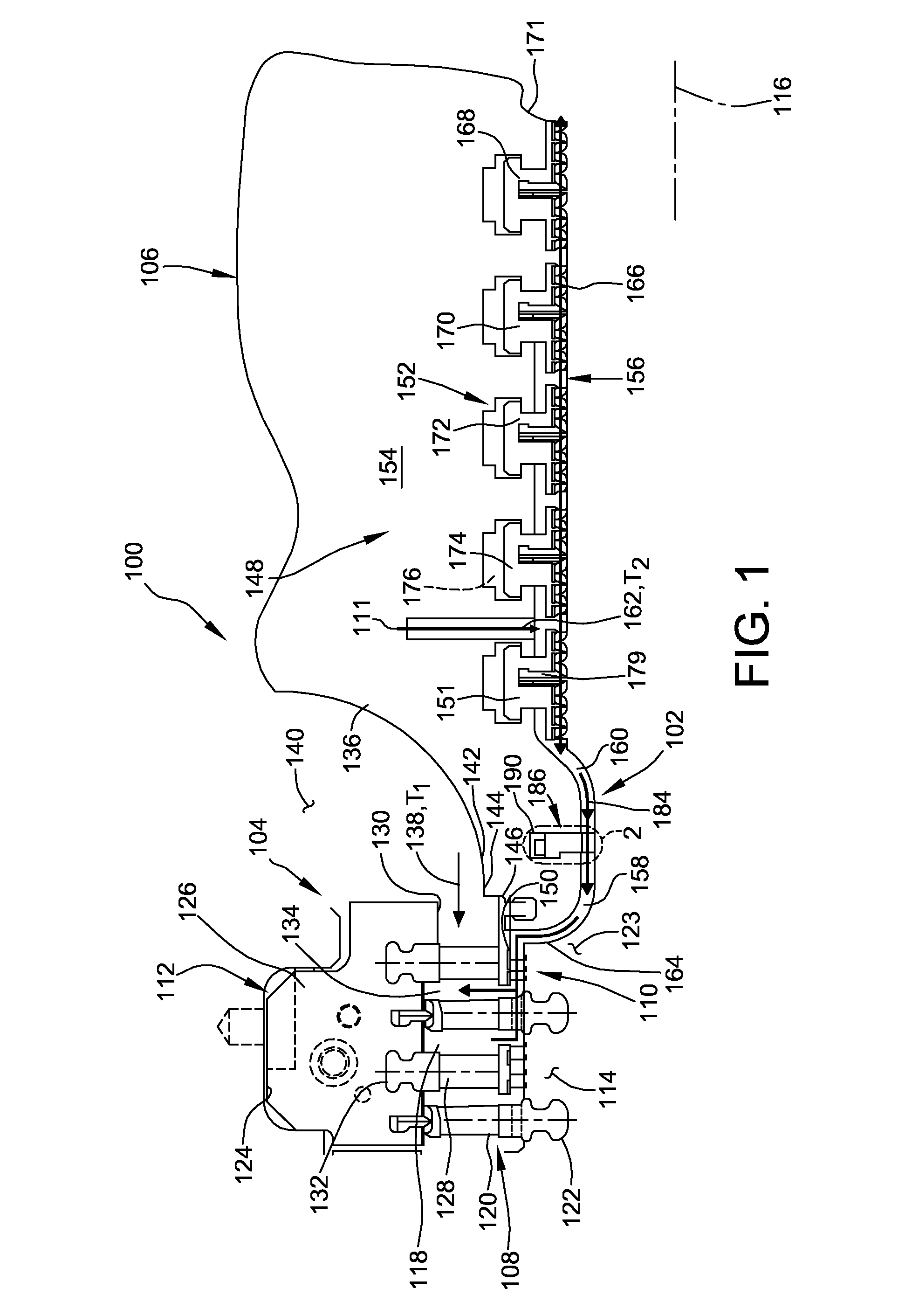
[0015]The embodiments described herein relate generally to steam turbines. More particularly, the embodiments relate to methods and systems for use in reducing and / or eliminating a swirl effect of cooling steam flowing within the steam turbine. It should be understood that the embodiments described herein for component cooling are not limited to turbine rotors, and further understood that the description and figures that utilize a steam turbine and rotors are for exemplary purposes only. Moreover, while the embodiments illustrate steam turbines and rotors, the embodiments described herein may be included in other suitable turbine components. Additionally, it should be understood that the embodiments described herein relating to flow paths need not be limited to turbine components. It should also be understood that the terms “primary flow path” and “first flow path” are used interchangeably; the terms “primary steam flow” and “first steam flow” are used interchangeably; the terms “co...


PUM

PropertyMeasurementUnit
Pressureaaaaaaaaaa
Velocityaaaaaaaaaa

Abstract

A steam turbine is provided. The steam turbine includes a housing and a steam inlet configured to discharge a primary steam flow within the housing. A stator is coupled to the housing and a rotor is coupled to the housing and located within the stator. The rotor and the stator are configured to define a primary flow path there between and in flow communication with the primary steam flow. The steam turbine includes a seal assembly coupled to the housing. The seal assembly includes a packing head and a plurality of seals. The packing head is configured to define a cooling flow path in flow communication with the rotor and configured to discharge a cooling steam flow toward the rotor. An anti-swirl device is coupled to the seal assembly and located between the rotor and the packing head.

Description

BACKGROUND OF THE INVENTION[0001]The embodiments described herein relate generally to steam turbines, and more particularly, to methods and systems for reducing a swirl effect of a cooling flow for a rotor of the steam turbine.[0002]As steam turbines rely on higher steam temperatures to increase efficiency, steam turbines are fabricated to withstand the higher steam temperatures so as not to compromise the useful life of the turbine. During a typical turbine operation, steam flows from a steam source through a housing inlet and substantially parallel to an axis of rotation along an annular hot steam path. Typically, turbine stages are positioned within the steam path such that the steam flows through vanes and blades of subsequent turbine stages. The turbine blades may be secured to a plurality of turbine wheels, where each turbine wheel is coupled to, or is formed, integral with the rotor shaft for rotation therewith. Alternatively, the turbine blades may be secured to a drum type ...

Claims


Application Information

Patent Timeline
IPC IPC(8): F01D9/04
CPCF01D9/045F01D9/06F01D9/065F01D11/003F01D11/005F01D25/24Y10T29/49316F01D5/081F01D5/187F01D11/00F01D25/12F01D5/08F01D11/02F05D2240/55
Inventor ZHENG, XIAOQINGFARINEAU, THOMAS JOSEPHELDRID, SACHEVEREL QUENTINBOWERS, JASON L.
Owner GENERAL ELECTRIC CO
Why Eureka
Try Eureka