Rotor off-take assembly

a technology of rotor and assembly, which is applied in the direction of machines/engines, stators, liquid fuel engines, etc., can solve the problems of little available kinetic head utilization, air swirling, pressure drop in the sealed cavity area,

Active Publication Date: 2017-01-05
GENERAL ELECTRIC CO
View PDF2 Cites 5 Cited by
  • Summary
  • Abstract
  • Description
  • Claims
  • Application Information

AI Technical Summary

Benefits of technology

[0010]According to exemplary embodiments, a rotor off-take assembly is provided by positioning an angled hole or aperture in a stator assembly. This angled hole provides improved pressure recovery and utilizes higher dynamic pressure to drive the bleed air flow into the off-take cavity.
[0011]According to some embodiments, a rotor off-take assembly for improved pressure recovery comprises a first rotor disk, including at least one first blade connected to the first rotor disk and extending radially outwardly, a second rotor disk, including at least one second blade connected to the second rotor disk and extending radially outwardly. At least one stator assembly is disposed between the first rotor disk and the second rotor disk. The stator assembly includes a flow surface generally extending from adjacent the first rotor disk assembly toward the second rotor disk assembly. The stator assembly includes an off-take aperture extending downwardly at a non-perpendicular angle through the flow surface wherein air passes through the off-take aperture of the stator assembly reducing swirl.

Problems solved by technology

However, one problem with the current state of the art is that as the air turns from the stator vane exit, the air encounters the turning structure of the adjacent rotor which causes swirl of the air and pressure drops in the sealed cavity area.
Additionally, since the air turns 90 degrees, very little available kinetic head is utilized to drive the flow of the bleed air to the off-take cavity.

Method used


Image

  • Rotor off-take assembly
  • Rotor off-take assembly
  • Rotor off-take assembly

Examples


Embodiment Construction

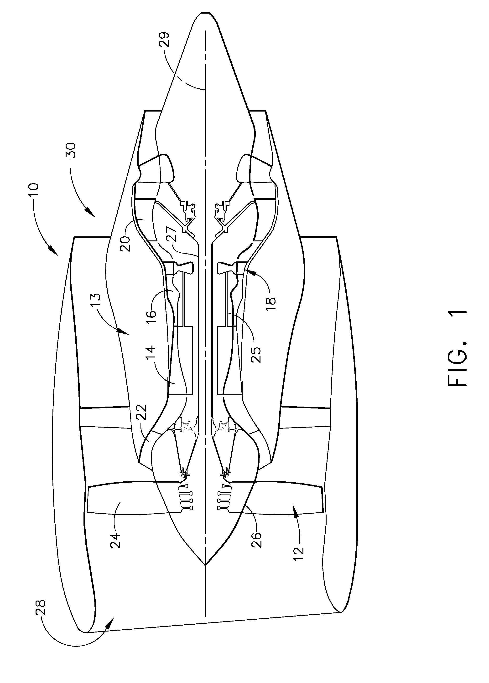
[0021]Reference now will be made in detail to embodiments provided, one or more examples of which are illustrated in the drawings. Each example is provided by way of explanation, not limitation of the disclosed embodiments. In fact, it will be apparent to those skilled in the art that various modifications and variations can be made in the present embodiments without departing from the scope or spirit of the disclosure. For instance, features illustrated or described as part of one embodiment can be used with another embodiment to still yield further embodiments. Thus, it is intended that the present invention covers such modifications and variations as come within the scope of the appended claims and their equivalents.

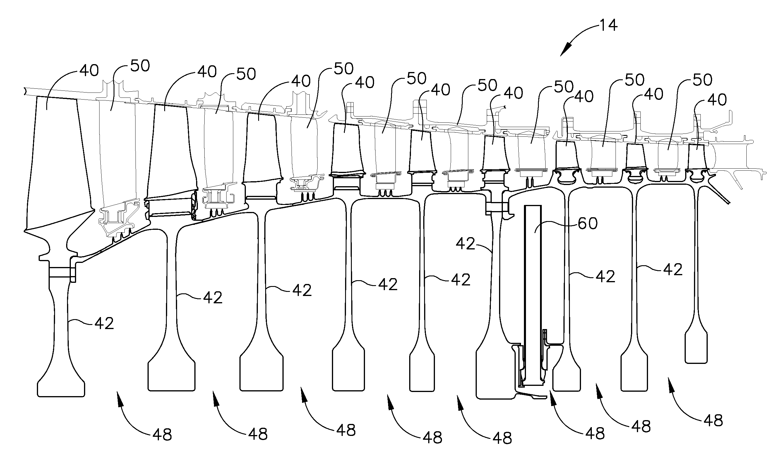
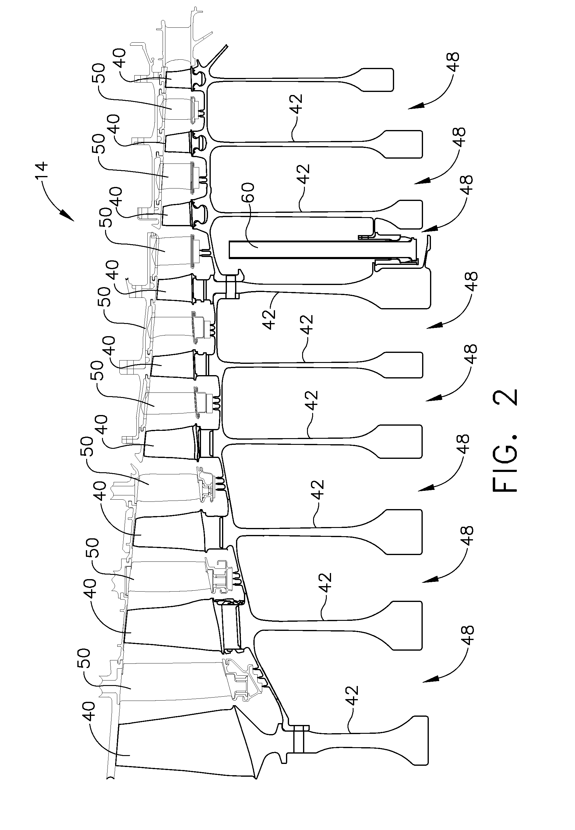
[0022]Referring now to FIGS. 1-7, various embodiments are depicted for an off-take for improved pressure recovery. The depicted embodiments show an off-take aperture disposed within the stator vanes of a high pressure compressor. However, the pressure recovery schemes...


PUM


Abstract

According to exemplary embodiments, a rotor off-take assembly is provided by positioning an angled hole or aperture in a stator assembly. This angled hole provides improved pressure recovery and utilizes higher dynamic pressure to drive the bleed air flow into the off-take cavity.

Description

BACKGROUND[0001]Present embodiments relate to a gas turbine engine. More particularly, but not by way of limitation, present embodiments relate to a rotor off-take aperture in the stator vane.[0002]In the gas turbine engine, air is pressurized in a compressor and mixed with fuel in a combustor for generating hot combustion gases which flow downstream through turbine stages. These turbine stages extract energy from the combustion gases. A high pressure turbine includes a first stage nozzle and a rotor assembly having a disk and a plurality of turbine blades. The high pressure turbine first receives the hot combustion gases from the combustor and includes a first stage stator nozzle that directs the combustion gases downstream through a row of high pressure turbine rotor blades extending radially outwardly from a first rotor disk. In a two stage turbine, a second stage stator nozzle is positioned downstream of the first stage blades followed in turn by a row of second stage turbine bl...

Claims


Application Information

Patent Timeline
Patent Type & Authority Applications(United States)
IPC IPC(8): F01D17/10F01D9/04F01D5/06
CPCF01D5/087F01D17/105F04D29/321F04D29/542F05D2240/80Y02T50/60F01D5/06F01D9/041F05D2220/32F05D2250/283
Inventor SUBRAMANIAN, SESHAPATTNAIK, SANTOSH KUMARSUNDARAN, SWAROOPN., CHANDRASEKARAN
Owner GENERAL ELECTRIC CO
Why Eureka
Try Eureka