Blind mate capacitively coupled connector

a capacitively coupled, blind-mate technology, applied in the direction of coaxial cables/analogue cables, coupling device details, coupling device connections, etc., can solve the problems of increasing the complexity of the resulting assembly, reducing the electrical performance of an entire rf system, and requiring additional assembly depth along the longitudinal axis

Active Publication Date: 2014-01-07
COMMSCOPE TECH LLC
View PDF89 Cites 28 Cited by
  • Summary
  • Abstract
  • Description
  • Claims
  • Application Information

AI Technical Summary

Benefits of technology

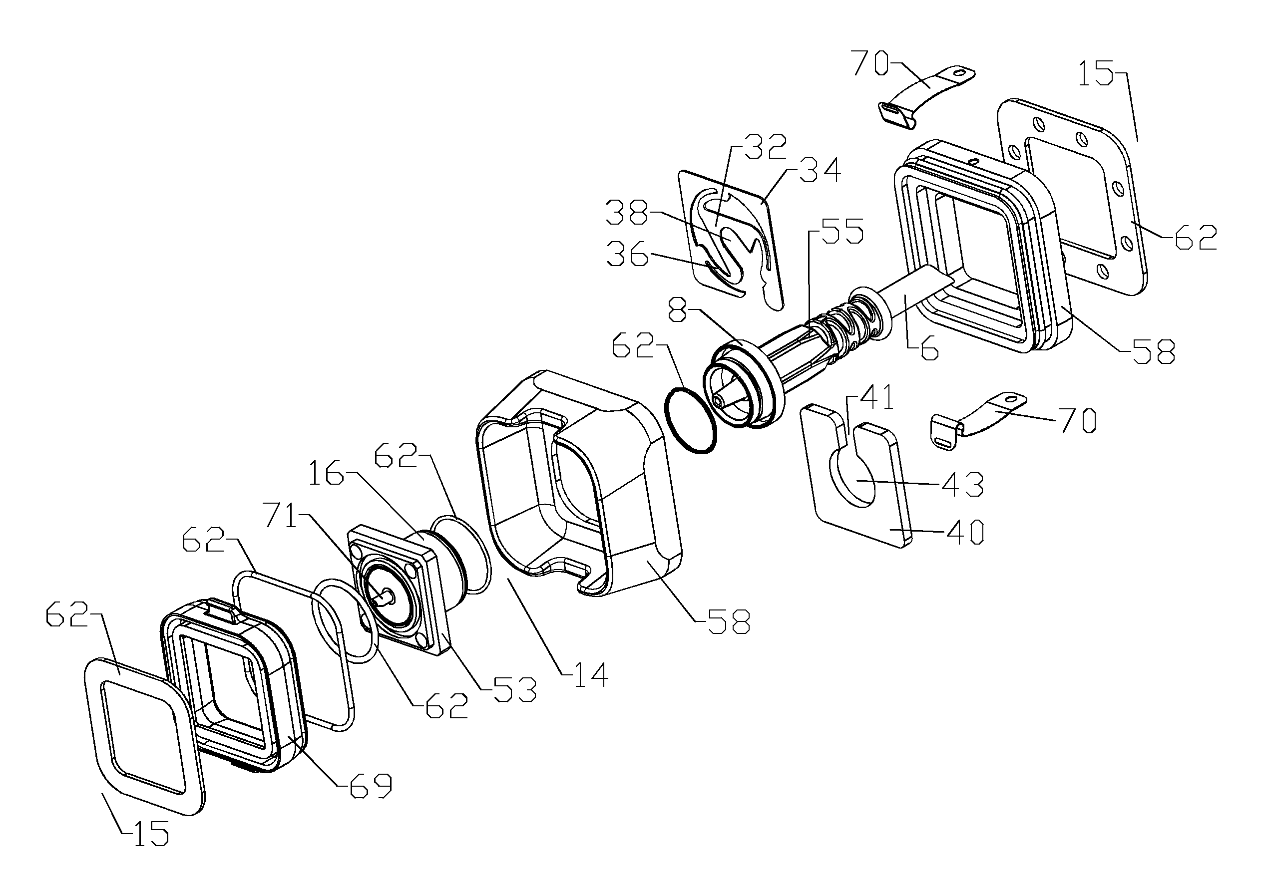
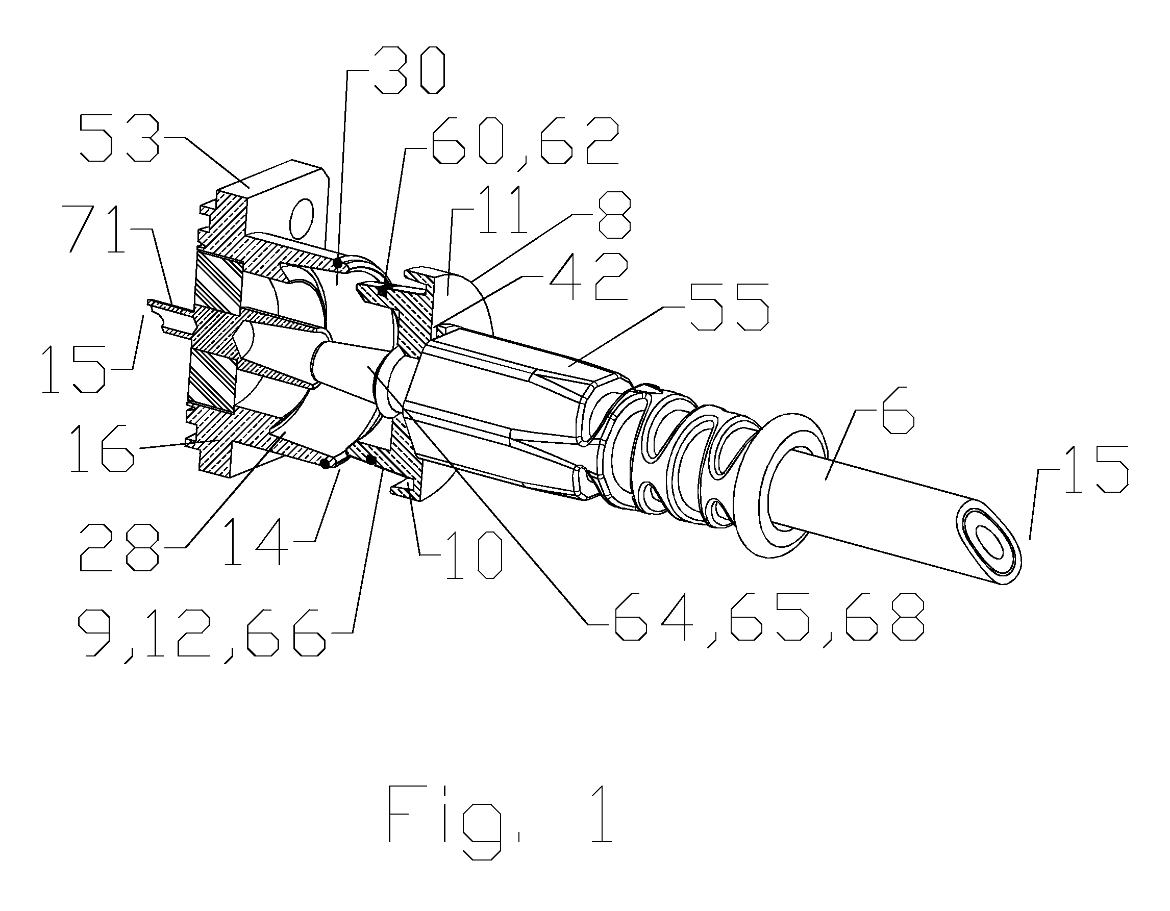
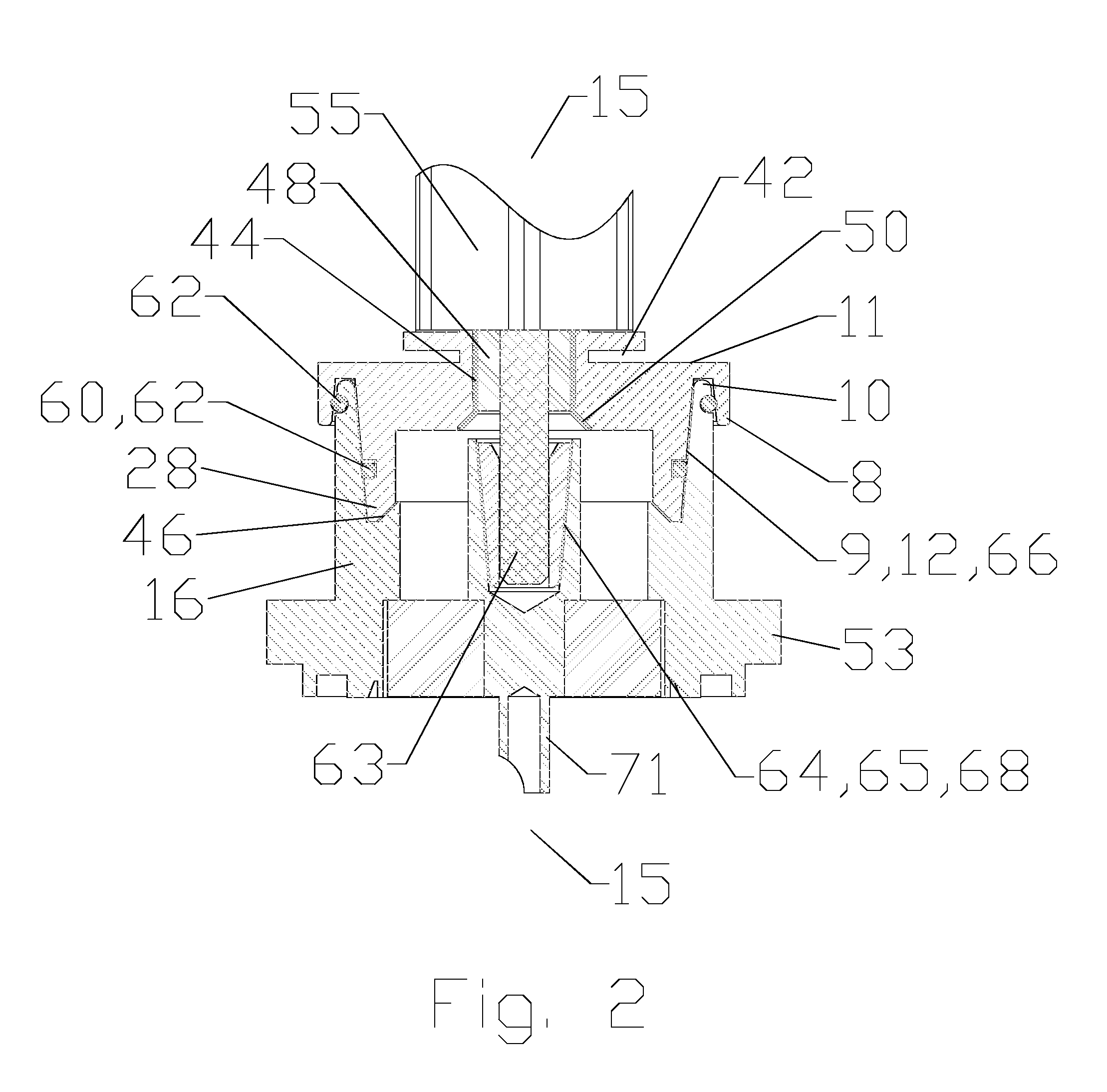
[0032]The male portion may further include a peripheral groove 10, open to the interface end 14, the peripheral groove 10 dimensioned to receive an outer diameter of the interface end 14 of the female portion 16. Thereby, the male outer conductor coupling surface 9 may extend from the peripheral groove 10 to portions of the male portion 8 contacting an inner sidewall 46 of the female portion 16, significantly increasing the surface area available for the male outer conductor coupling surface 9.
[0064]The range of radial movement enables the male portion(s) 8 to adapt to accumulated dimensional variances between linkages, mountings and / or associated interconnections such as additional ganged connectors, enabling, for example, swing arm blind mating between one or more male portion 8 and a corresponding number of female portion 16. Further, the generally conical mating surfaces provide an additional self-aligning seating characteristic that increases a minimum sweep angle before interference occurs, for example where initial insertion during mating is angled with respect to a longitudinal axis of the final interconnection, due to swing arm based arc engagement paths.

Problems solved by technology

PIM is an important interconnection quality characteristic as PIM generated by a single low quality interconnection may degrade the electrical performance of an entire RF system.
Prior blind mate connector assemblies may include one or more helical coil springs, which may increase the complexity of the resulting assembly and / or require additional assembly depth along the longitudinal axis.

Method used


Image

  • Blind mate capacitively coupled connector
  • Blind mate capacitively coupled connector
  • Blind mate capacitively coupled connector

Examples


Embodiment Construction

[0026]The inventors have recognized that PIM may be generated at, in addition to the interconnections between the inner and outer conductors of a coaxial cable and each coaxial connector, the electrical interconnections between the connector interfaces of mating coaxial connectors.

[0027]Further, threaded interconnection interfaces may be difficult to connect in high density / close proximity connector situations where access to the individual connector bodies is limited. Even where smaller diameter cables are utilized, standard quick connection interfaces such as BNC-type interconnections may provide unsatisfactory electrical performance with respect to PIM, as the connector body may pivot laterally along the opposed dual retaining pins and internal spring element, due to the spring contact applied between the male and female portions, according to the BNC interface specification. Further, although BNC-type interconnections may be quick connecting, the requirement of twist-engaging th...


PUM


Abstract

A connector with a capacitively coupled connector interface for interconnection with a female portion is provided with an annular groove, with a sidewall, open to an interface end of the female portion. A male portion is provided with a male outer conductor coupling surface at an interface end, covered by an outer conductor dielectric spacer. The male portion is retained with a range of radial movement, with respect to a longitudinal axis of the male portion, by a bias web of a float plate. The male outer conductor coupling surface is dimensioned to seat, spaced apart from the sidewall by the outer conductor dielectric spacer, within the annular groove, when the male portion and the female portion are in an interlocked position.

Description

BACKGROUND[0001]1. Field of the Invention[0002]This invention relates to electrical cable connectors. More particularly, the invention relates to connectors with a blind mateable capacitively coupled connection interface.[0003]2. Description of Related Art[0004]Coaxial cables are commonly utilized in RF communications systems. Coaxial cable connectors may be applied to terminate coaxial cables, for example, in communication systems requiring a high level of precision and reliability.[0005]Connector interfaces provide a connect and disconnect functionality between a cable terminated with a connector bearing the desired connector interface and a corresponding connector with a mating connector interface mounted on an apparatus or a further cable. Prior coaxial connector interfaces typically utilize a retainer provided as a threaded coupling nut which draws the connector interface pair into secure electro-mechanical engagement as the coupling nut, rotatably retained upon one connector, ...

Claims


Application Information

Patent Timeline
Patent Type & Authority Patents(United States)
IPC IPC(8): H01R13/64
CPCH01R24/38H01R9/05H01Q1/00Y02E40/64H01G2/10H01B11/18
Inventor VAN SWEARINGEN, KENDRICKPAYNTER, JEFFREY D
Owner COMMSCOPE TECH LLC
Why Eureka
Try Eureka