Adjusting VGA analog gain for misaligned servo sectors in a disk drive

a technology of servo sector and vga analog gain, which is applied in the field of disk drive technology, can solve the problems of further distortion of burst profile, further misalignment of track misalignment in seamless pattern, and introduction of burst readback measurement error, so as to improve track squeeze measurement, reduce measurement noise, and accurately measure the effect of vga chang

Inactive Publication Date: 2014-01-07
WESTERN DIGITAL TECH INC
View PDF28 Cites 8 Cited by
  • Summary
  • Abstract
  • Description
  • Claims
  • Application Information

AI Technical Summary

Benefits of technology

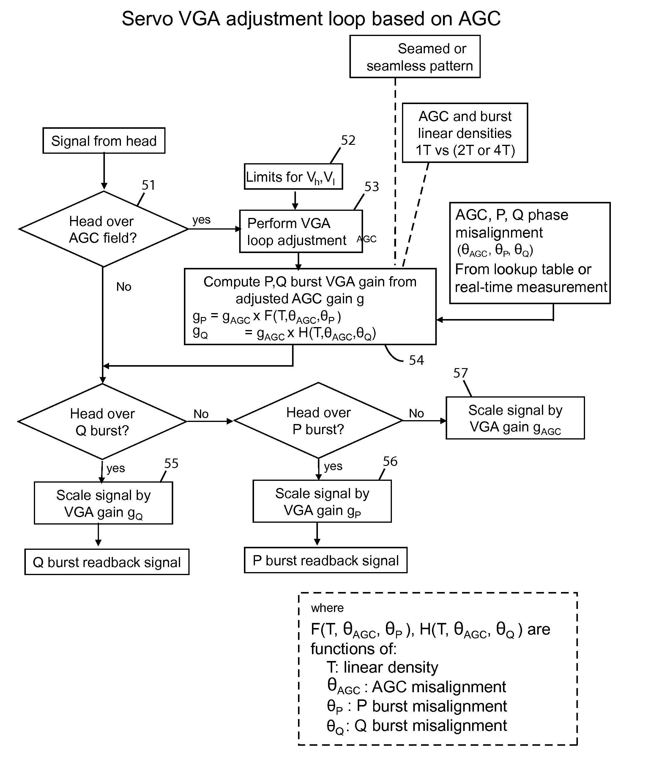
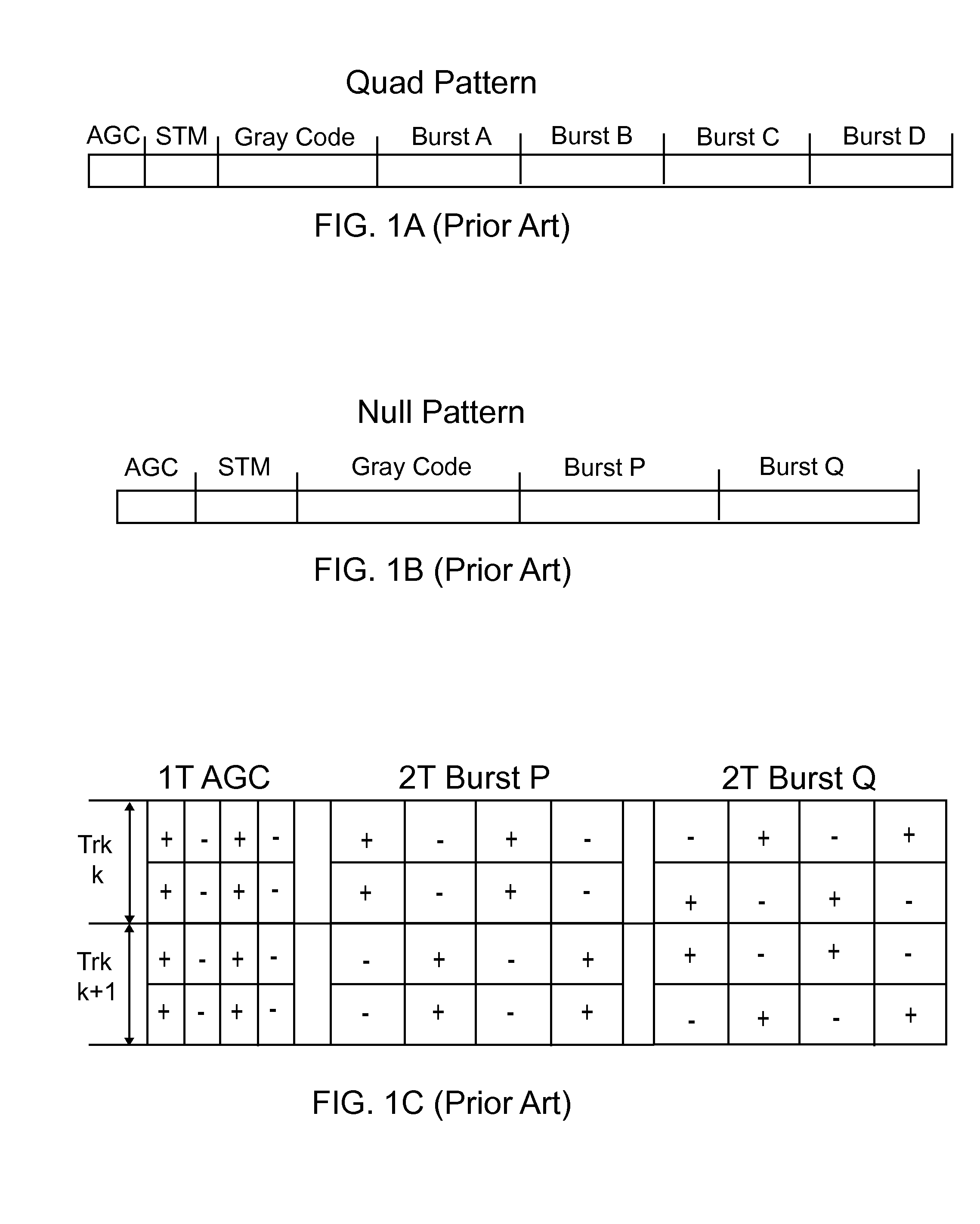
[0016]The invention addresses the problem of phase mismatch causing different gain loss for 1T versus 2T versus 4T signals where T is the time period corresponding to the linear bit density. VGA gain is corrected (adjusted) for difference in AGC versus burst frequencies for misaligned tracks. The VGA feedback loop makes adjustments for gain errors induced by phase mismatch. The invention provides correct cross-track burst profiles for servo sectors with significant phase mismatch with respect to adjacent tracks. Gain for the burst signal is adjusted to take into account half-frequency of ABCD or PQ burst signals. The results are reduced measurement noise for servo metrics that are based on cross-track burst profile / VGA values and direct improvement in track squeeze measurement. The contribution of down-track phase shift from squeeze metric is removed. The invention provides accurate measurement of VGA change due to fly height / magnetic effects and removes VGA gain change arising from phase mismatch. Since 2T or 4T bursts can result in voltage saturation if large erroneous gain is selected in VGA loop, AGC saturation for servo with large phase mismatch is prevented which allows more accurate tuning of VGA gain.

Problems solved by technology

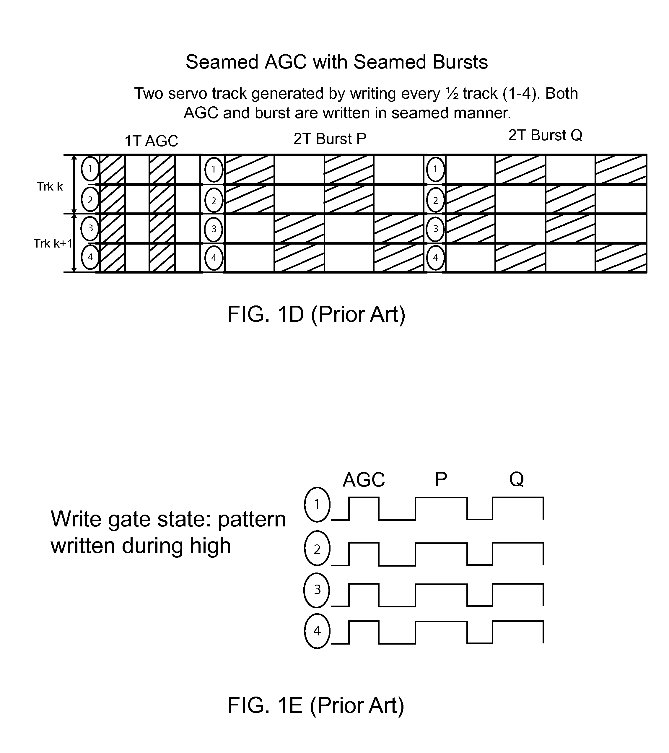
The voltage readback will vary based on the amount of phase misalignment and thereby introduce error in burst readback measurement.
As illustrated in FIGS. 4A-B, track misalignment in seamless patterns is further complicated where AGC, P and Q bursts can have different misalignment.
This results in further distortion in burst profile where one burst has same misalignment as AGC while other burst does not.

Method used


Image

  • Adjusting VGA analog gain for misaligned servo sectors in a disk drive
  • Adjusting VGA analog gain for misaligned servo sectors in a disk drive
  • Adjusting VGA analog gain for misaligned servo sectors in a disk drive

Examples


Embodiment Construction

[0044]Accurate cross-track servo burst (ABCD) profile is required for various servo related error scans. For example, track squeeze measurement is based on change in burst profile due to cross-track squeeze as shown in FIGS. 1L, 1M, 1N which describe the squeeze measurement technique based on recording the changes in burst profile induced by cross-track squeeze. A squeeze error occurs when the width of a data track is too narrow and causes partial erasure of adjacent data tracks. As shown in graph in FIG. 1N, the amplitude of the P and Q burst signals is reduced by the track squeeze.

[0045]Other examples of servo calibration steps that are based on servo burst profiles include estimation of read / write head offset and determination of servo metric as shown in FIGS. 1O, 1P. In these processes, burst crossing signal and ratio of burst amplitudes are used to adjust servo related parameters. FIG. 1O illustrates the read / write (Rd / Wr) offset based on the burst crossing signal which can be ...


PUM

PropertyMeasurementUnit
phase misalignmentaaaaaaaaaa
linear densitiesaaaaaaaaaa
linear densityaaaaaaaaaa

Abstract

Embodiments of the invention include data storage system with a servo system with a VGA feedback loop that corrects gain errors for servo bursts arising from track phase misalignment and difference in frequencies between AGC and servo bursts for seamed and seamless servo patterns. After the servo fields have been written as part of the manufacturing process, in one embodiment measurements of phase misalignment are made and recorded in nonvolatile memory for use during normal operation of the drive. One embodiment includes measuring misalignment using relative signal magnitudes from test bursts with various linear densities written in a data area during the self-servo writing process. In an alternative embodiment the measurements of phase misalignment can be made real-time during normal operation of the drive.

Description

FIELD OF THE INVENTION[0001]The present invention relates generally to disk drive technology, and more particularly to means for processing servo signals generated by magnetic servo patterns on a rotating disk.BACKGROUND[0002]Magnetic disk drive systems typically include one or more sliders that contain read and write heads that are used to read and write data in thin film magnetic media on one of more rotating disks. The sliders are mounted on a movable actuator that is positioned by a servo system over the rotating disk using a VCM. The information in the thin film magnetic material on each disk surface is organized into concentric circular tracks that are further divided into angularly spaced servo sectors. Each sector has servo information permanently recorded therein as a part of the manufacturing process. The user data in the sector follows the servo information. The servo information typically includes track and sector location information, automatic gain control (AGC) fields...

Claims


Application Information

Patent Timeline
Patent Type & Authority Patents(United States)
IPC IPC(8): G11B5/596
CPCG11B5/59688G11B5/59627G11B5/59655G11B5/59666G11B2020/1281G11B5/5534
Inventor DHANDA, ABHISHEKHIRANO, TOSHIKISEMBA, TETSUO
Owner WESTERN DIGITAL TECH INC
Why Eureka
Try Eureka