Method for measuring deviation of joint position of member and method for producing spark plug

a technology of joint position and measurement method, which is applied in the manufacture of spark plugs, instruments, mechanical measuring arrangements, etc., can solve the problems of deteriorating measurement accuracy of deviation, variation in quality, and inability to objectively numerically evaluate deviation from optimal igniting position of ground electrodes, etc., to prevent the effect of quality variation

Active Publication Date: 2014-01-14
NGK SPARK PLUG CO LTD
View PDF6 Cites 2 Cited by
  • Summary
  • Abstract
  • Description
  • Claims
  • Application Information

AI Technical Summary

Benefits of technology

[0009]The present invention has been achieved in view of the above-mentioned problems, and an object of the present invention is to improve measurement accuracy of a deviation from a joint target position of a member joined to a measuring object.
[0028]According to the manufacturing method of Aspect 8, the spark plug is manufactured in such a manner that the deviation of the electrode from the joint target position is measured based on the angle between the straight line that connects the axis of the metallic shell to at least one measuring point and the reference straight line that connects the axis to the reference portion. Further, the insulator is joined to the metallic shell in which the deviation is judged to be within the allowable range. Therefore, variation in quality of the spark plug can be prevented.

Problems solved by technology

However, no objective numerical evaluation of a deviation from an optimal igniting position of the ground electrode was inspected.
Even though the position of the ground electrode is the same, an accept / reject judgment tends to be inconsistent according to an inspector.
This causes deterioration in measurement accuracy of the deviation and variation in quality.
The above-mentioned problems are common not only for a metallic shell of spark plugs but also for various products having a member joined to a predetermined location thereof.

Method used


Image

  • Method for measuring deviation of joint position of member and method for producing spark plug
  • Method for measuring deviation of joint position of member and method for producing spark plug
  • Method for measuring deviation of joint position of member and method for producing spark plug

Examples


first embodiment

A. First Embodiment

[0042]A1. Composition of Spark Plug:

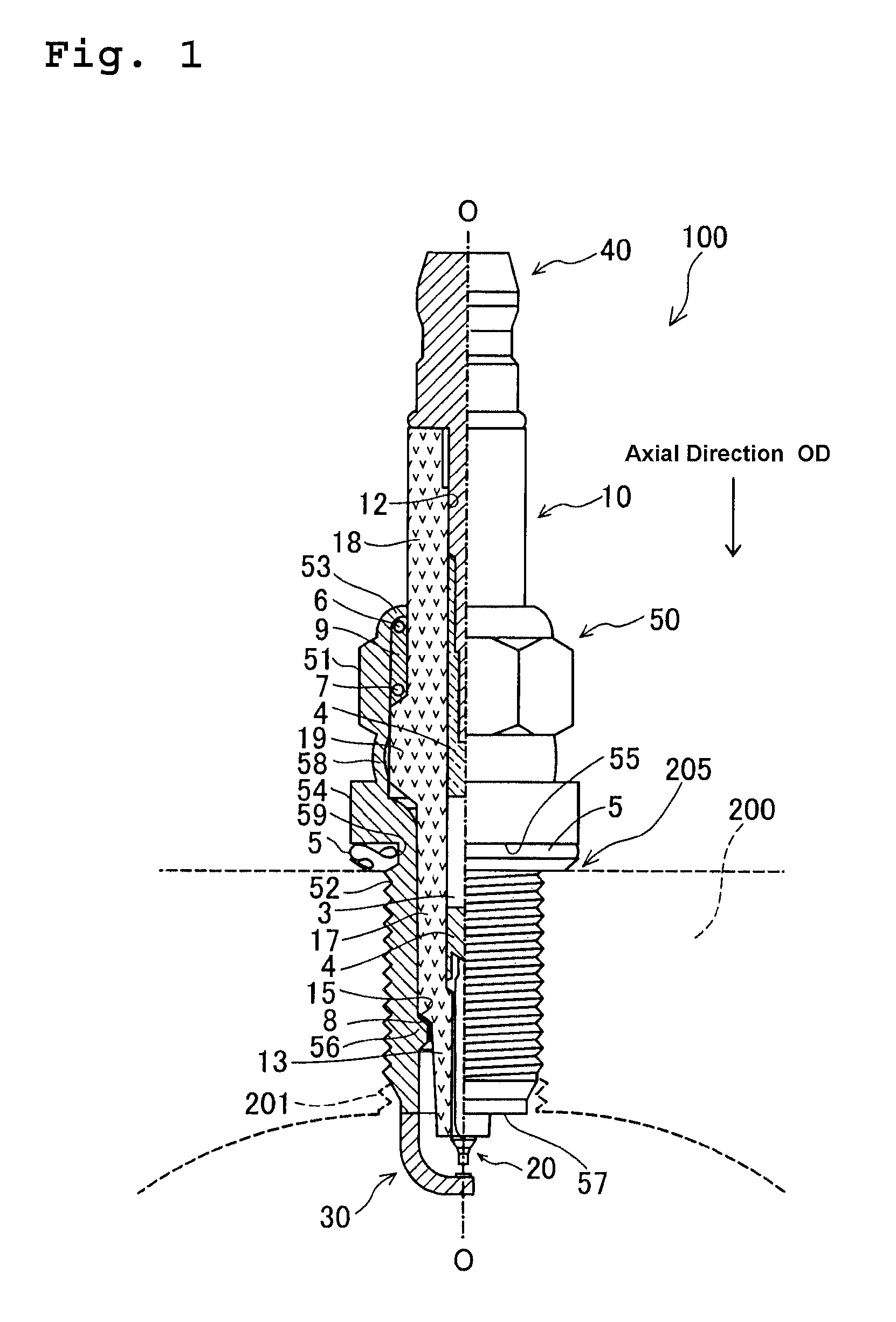
[0043]Hereafter, an embodiment of the present invention will be described. FIG. 1 is a partially sectioned view of a spark plug 100 according to a first embodiment. Notably, in FIG. 1, the spark plug 100 is depicted in such a manner that an axial direction OD of the spark plug 100 coincide with the vertical direction in FIG. 1. Further, in the following description, the lower side of FIG. 1 will be referred to as a front end side of the spark plug 100, and the upper side of FIG. 1 will be referred to as a rear end side of the spark plug 100.

[0044]As shown in FIG. 1, the spark plug 100 is comprised of a ceramic insulator 10 serving as an insulator, a metallic shell 50 holding therein the ceramic insulator 10, a center electrode 20 held in the ceramic insulator 10 in the axial direction OD, a ground electrode 30, and a terminal fitting 40 formed in the rear end portion of the ceramic insulator 10.

[0045]As is well known, the cerami...

second embodiment

B. Second Embodiment

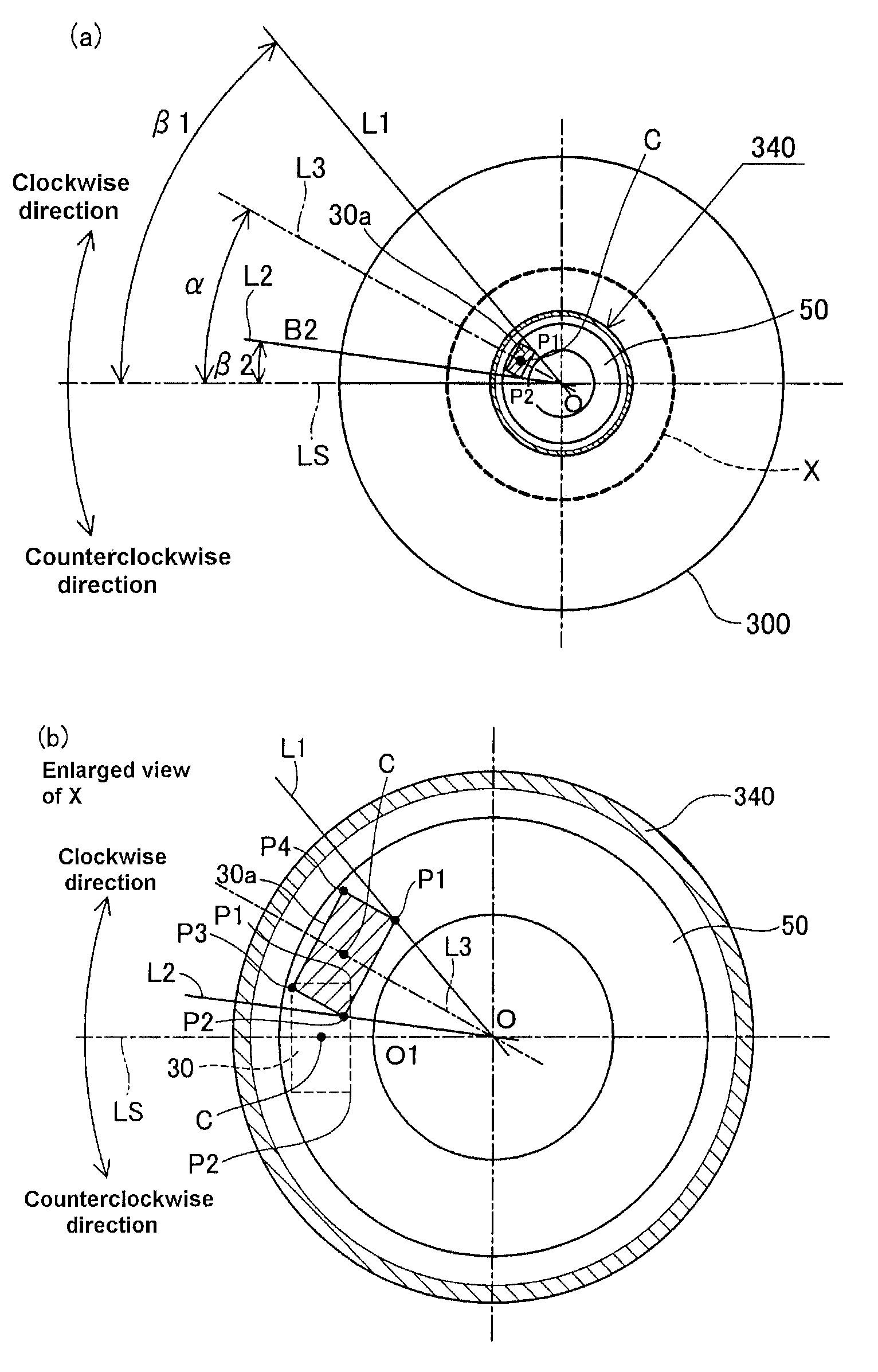
[0081]In the first embodiment, the deviation of the ground electrode 30 is measured with the numerical terms by analyzing the image data of the projection view. In the second embodiment, an inspector conducts visual inspection and judges whether or not the joint position of the ground electrode 30 is within a predetermined allowable angle range. Thereafter, the measurement of the deviation is conducted only to the metallic shell 50 having the joint position of the ground electrode 30 within the allowable angle range. In the second embodiment, the deviation of the ground electrode 30 is measured based on the allowable angle range indicated on a measurement face of the female thread jig.

[0082]B1. Measuring Method of Deviation of Ground Electrode from Joint Target Position:

[0083]FIG. 11 is a top view showing the measurement face 360a of the female thread jig 300a in the second embodiment. FIG. 11 shows a state where the metallic shell 50 is engaged with the female t...


PUM


Abstract

In a method for measuring deviation of a ground electrode from an optimal igniting position, a metallic shell is engaged with a female thread jig. Then the axis O of the metallic shell, a predetermined first measuring point P1 and a predetermined second measuring point P2 on a front end face of the ground electrode are detected. Then, a circumferential angle β1 formed between a reference straight line “LS” connecting O to the optimal igniting position O1, and a first straight line L1 which connects O to P1 is measured, followed by a measurement of a circumferential angle β2 formed between LS and a second straight line L2 connecting O to P2 Thereafter, the deviation of the ground electrode from O1 is measured as a circumferential angle “α” between “LS” and a third straight line L3 connecting the axis O to the center C of the front end face.

Description

CROSS-REFERENCE TO RELATED PATENT APPLICATIONS[0001]This application is a U.S. National Phase Application under 35 U.S.C. §371 of International Patent Application No PCT / JP2010 / 000602, filed Feb. 2, 2010, and claims the benefit of Japanese Patent Application No. 2009-024110, filed Feb. 4, 2009, all of which are incorporated by reference herein. The International Application was published in Japanese on Dec. 8, 2010 as International Publication No. WO / 2010 / 089992 under PCT Article 21(2).FIELD OF THE INVENTION[0002]The present invention relates to a method for measuring a deviation of a member joined to a measuring object from a joint target position using a female thread jig, particularly a deviation of an electrode position of a spark plug, and further relates to a method for manufacturing a spark plug which adapts said measuring method.BACKGROUND OF THE INVENTION[0003]A metallic shell of a spark plug has a center electrode and a ground electrode which are positioned so as to face e...

Claims


Application Information

Patent Timeline
Patent Type & Authority Patents(United States)
IPC IPC(8): G01B11/14H01T21/02
CPCG01B5/003G01B11/26H01T21/06G01B11/00
Inventor OZEKI, ATSUSHI
Owner NGK SPARK PLUG CO LTD
Why Eureka
Try Eureka