Head suspension and method of manufacturing head suspension

a head suspension and head technology, applied in the field of head suspension, can solve the problems of piezoelectric elements, insufficient electrical insulation, ooze and spread of applied adhesive,

Active Publication Date: 2014-01-14
NHK SPRING CO LTD
View PDF8 Cites 31 Cited by
  • Summary
  • Abstract
  • Description
  • Claims
  • Application Information

AI Technical Summary

Benefits of technology

[0014]An object of the present invention is to provide a head suspension capable of properly maintaining electrical insulation between a piezoelectric element and an attaching part of the head suspension to which the piezoelectric element is attached and sufficiently perform original functions of the head suspension. Another object of the present invention is to provide a method of manufacturing such a head suspension.
[0016]This aspect of the present invention employs the plurality of adhesive layers to fix the piezoelectric element to the support that supports an electrode face of the piezoelectric element. One of the adhesive layers that is in contact with the support is electrically insulative. This aspect secures electrical insulation between the piezoelectric element and the attaching part and allows the head suspension to fully function.

Problems solved by technology

An important issue for the head suspension employing the dual actuator system is how to mount the piezoelectric elements on the head suspension.
If the quantity of the adhesive applied into the gap is too small, electrical insulation will be insufficient between the piezoelectric elements and the actuator base.
If the adhesive quantity is too large, the applied adhesive will ooze and spread.
Namely, if the applied adhesive is too small, an insulation failure will occur between the piezoelectric elements and the actuator base, to deteriorate functions of the head suspension.
If the applied adhesive is too large, the adhesive will ooze and spread to reach the flexure of the load beam, to deteriorate the rigidity balance and vibration characteristic of the head suspension.

Method used


Image

  • Head suspension and method of manufacturing head suspension
  • Head suspension and method of manufacturing head suspension
  • Head suspension and method of manufacturing head suspension

Examples


Embodiment Construction

[0027]Head suspensions and methods of manufacturing head suspensions according to embodiments and modifications of the present invention will be explained in detail with reference to the drawings.

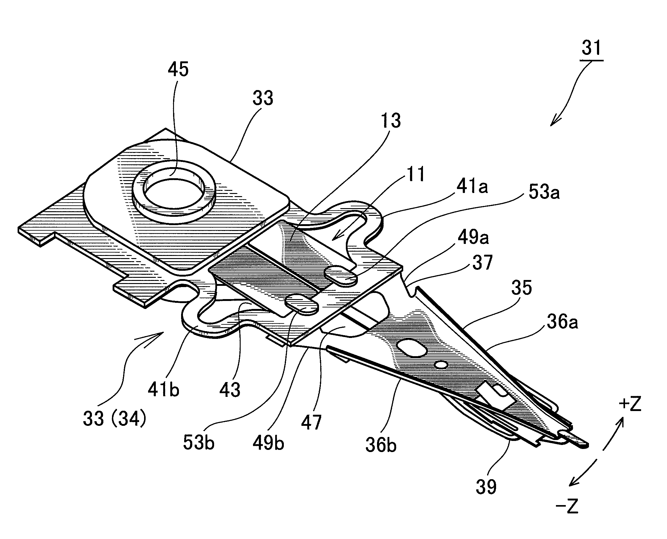
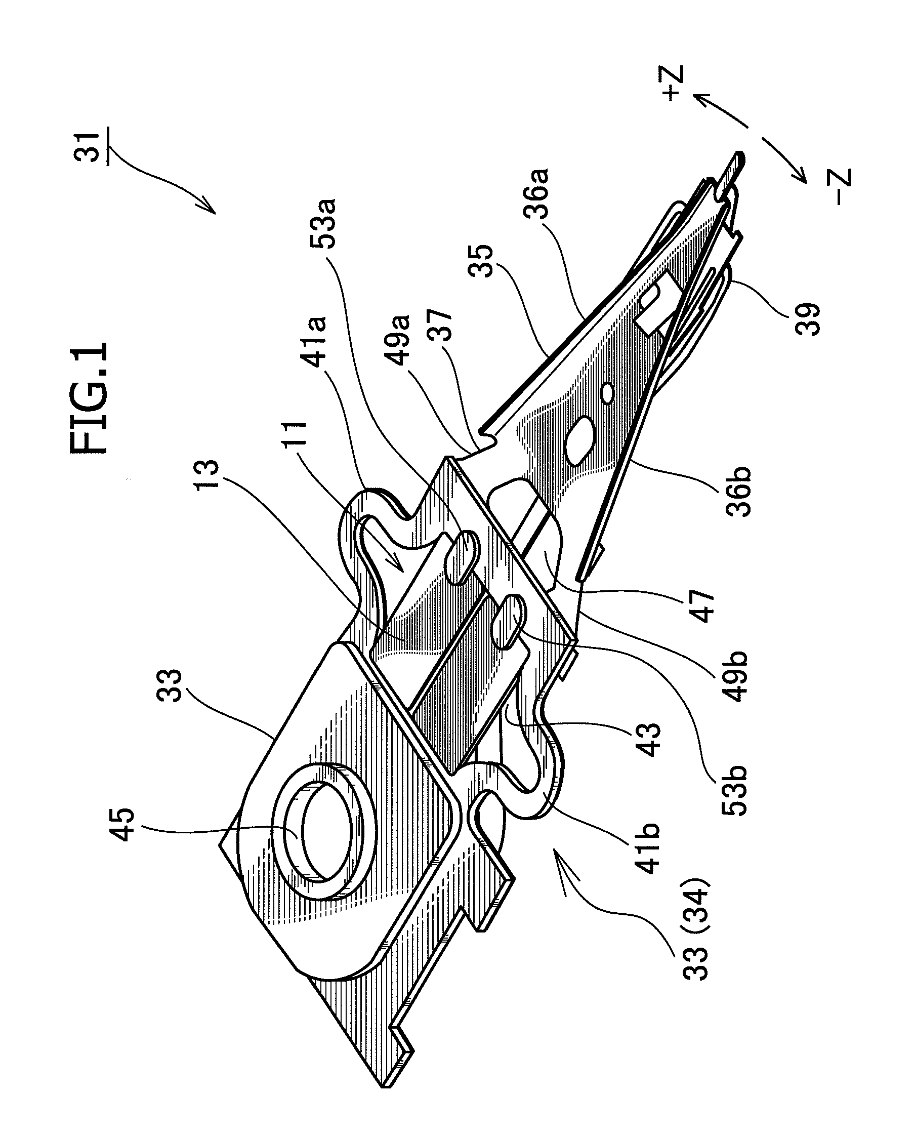
[0028]FIG. 1 is a perspective view illustrating a head suspension 31 according to an embodiment of the present invention.

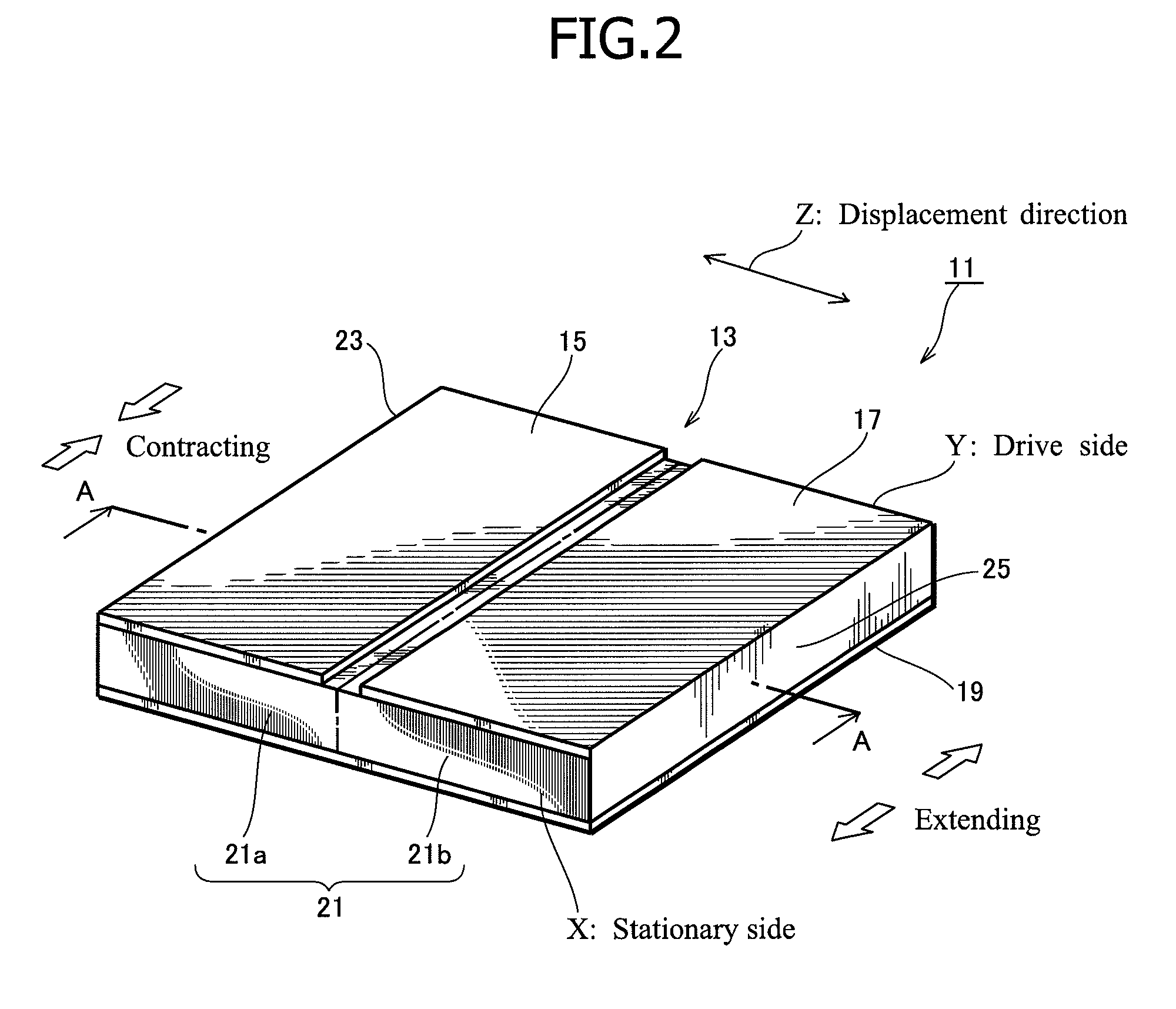
[0029]The head suspension 31 includes a piezoelectric actuator 11 consisting of a piezoelectric element 13 that deforms in response to a voltage applied thereto, a base plate 33 (corresponding to the “base” stipulated in the claims), a load beam 35, a connection plate 37 functioning as a hinge, and the like.

[0030]The base plate 33 has an opening 43 (corresponding to the “attaching part” stipulated in the claims) in which the piezoelectric element 13 is embedded. The piezoelectric element 13 deforms in response to an applied voltage, to move a front end of the load beam 35 in a sway direction, i.e., a widthwise direction of the head suspension 31.

[0031]The base plate 33 is...


PUM

PropertyMeasurementUnit
thicknessaaaaaaaaaa
thicknessaaaaaaaaaa
thicknessaaaaaaaaaa

Abstract

A head suspension 31 has a piezoelectric element 13 that deforms in response to a voltage applied thereto, a base plate 33 having an attaching part to which the piezoelectric element 13 is attached, and a load beam 35 having a flexure 39. A front end of the load beam 35 moves in a sway direction according to the deformation of the piezoelectric element 13. The head suspension 31 includes adhesives that attach the piezoelectric element 13 to the attaching part. The adhesives are applied to and hardened at the attaching part one by one. At least one of the adhesives that is first applied to and hardened at the attaching part is electrically insulative.The head suspension 31 properly maintains electric insulation between the piezoelectric element 13 and the attaching part, sufficiently demonstrates original functions, and secures a rigidity balance and proper vibration characteristic.

Description

BACKGROUND OF THE INVENTION[0001]1. Field of the Invention[0002]The present invention relates to a head suspension having a piezoelectric element that is attached to the head suspension with an electrically insulative adhesive and is deformed in response to a voltage applied thereto. The present invention also relates to a method of manufacturing such a head suspension.[0003]2. Description of Related Art[0004]Small-sized, precision information devices are rapidly advancing, and for such devices, needs are increasing for micro-actuators capable of conducting positioning control for very small distances. The devices that particularly need such micro-actuators include optical systems for correcting focuses and inclination angles, ink jet printers for controlling ink heads, and magnetic disk drives for controlling magnetic heads.[0005]The magnetic disk drives have an urgent issue to solve, i.e., increasing storage capacity. The storage capacity of a magnetic disk drive will increase if ...

Claims


Application Information

Patent Timeline
Patent Type & Authority Patents(United States)
IPC IPC(8): G11B5/56
CPCG11B5/4873G11B5/5552G11B5/4826Y10T156/10
Inventor ANDO, TOSHIKIFUCHINO, HIDEKIFUKUDA, TSUTOMUSUGIMOTO, EMI
Owner NHK SPRING CO LTD
Why Eureka
Try Eureka