Material-handling bucket with scraper blade

a technology of scraper blade and material bucket, which is applied in the direction of lifting devices, machines/dredgers working methods, constructions, etc., can solve the problems of uneven material removal, not allowing significant material accumulation, and not being optimally designed for scraping or skimming buckets, etc., to achieve effective opening area expansion, simple, efficient, cost-effective

Inactive Publication Date: 2014-01-21
TULIBASKI BEN
View PDF29 Cites 2 Cited by
  • Summary
  • Abstract
  • Description
  • Claims
  • Application Information

AI Technical Summary

Benefits of technology

[0009]The present invention provides a simple, efficient, cost-effective and reliable material handling bucket assembly usable with construction or agricultural earth moving and handling motive power equipment. The bucket assembly can include both scraper and grader blades cooperatively movable and operable to allow the bucket to be used in a traditional manner, or to be rapidly converted to scraper or grading applications. Scraper and grader blades are rotatably mounted to the bucket adjacent an enlarged opening formed through the bottom wall of the bucket. When the bucket assembly is used in a traditional conventional manner, the scraper and grader blades cooperatively close or substantially close the opening through the bottom wall of the bucket. By simple rotation of the scraper blade relative to the bottom wall opening, the bucket can rapidly be transitioned for use as a scraper, wherein the scraper blade engages and removes ground soil from a ground surface and directs such removed soil into a collection chamber of the bucket through the opening in the bottom wall. The grader blade or alternative panel type member rotatably position adjacent the enlarged opening enables the effective opening area to be enlarged in response to the volume of removed material being directed toward the opening. The scraper blade concept also applies to excavation bucket designs for selective removal of material from trenches for forming, for example, bottom trench configurations of varied geometrical cross-sections.

Problems solved by technology

However, the buckets are often used for many of the above-described tasks for which they are not optimally designed.
For example, such buckets are not typically optimally designed for scraping or skimming, grading, or scarifying surface material.
With conventional bucket designs, when the primary blade of the bucket is used for scraping operations, the blade tends to dig into the material surface when the blade is advanced in a forward direction of the bucket, providing uneven material removal.
Typical buckets do not allow for significant material to be accumulated behind the bucket when used in this manner, and the rear surfaces of conventional buckets are not designed and reinforced for extended use in this manner.
Such operation places significant torque on the bucket and excessive wear and tear on the hydraulic cylinders and linkage that control the bucket rotation.
Such designs are fairly cumbersome and relatively expensive to implement, and do not optimally provide for simultaneous uniform scraping removal and retention of soil or material from a surface.
The forward blade forms a front surface of and closes the front opening of the bucket such that it is not usable as a conventional front-end loader bucket.
Such design requires skilled operator coordination of the relative positions of the first and second blades and does not enable the bucket to be used for multipurpose loading and transporting functions through front-end loading thereof.
Such designs, however, are generally cumbersome, often require work to be delayed while the special attachment is applied to the bucket, and generally do not provide the flexibility of use of the bucket for its primary intended excavation process when such trench shaping process is not needed or desired.

Method used


Image

  • Material-handling bucket with scraper blade
  • Material-handling bucket with scraper blade
  • Material-handling bucket with scraper blade

Examples


Embodiment Construction

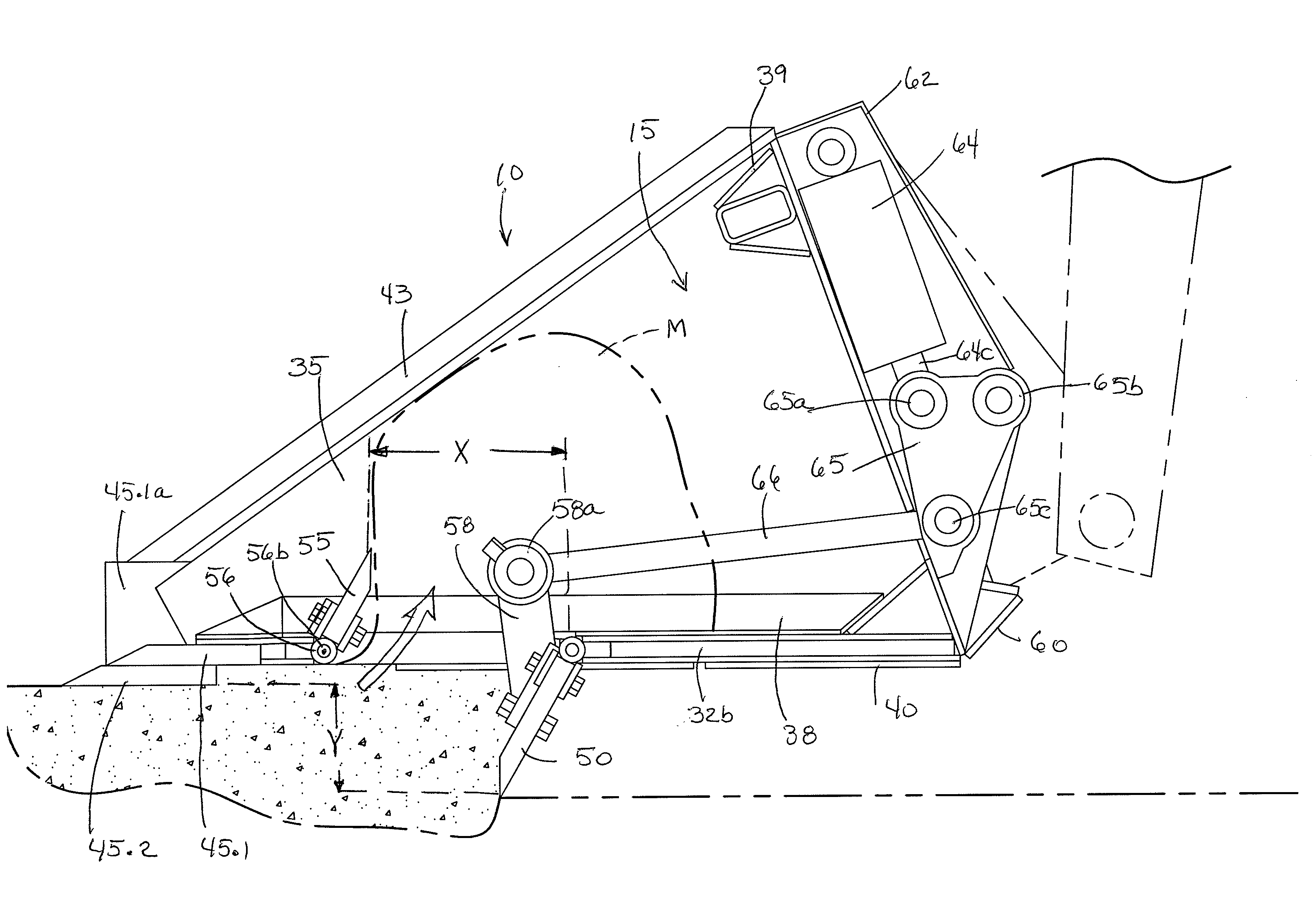
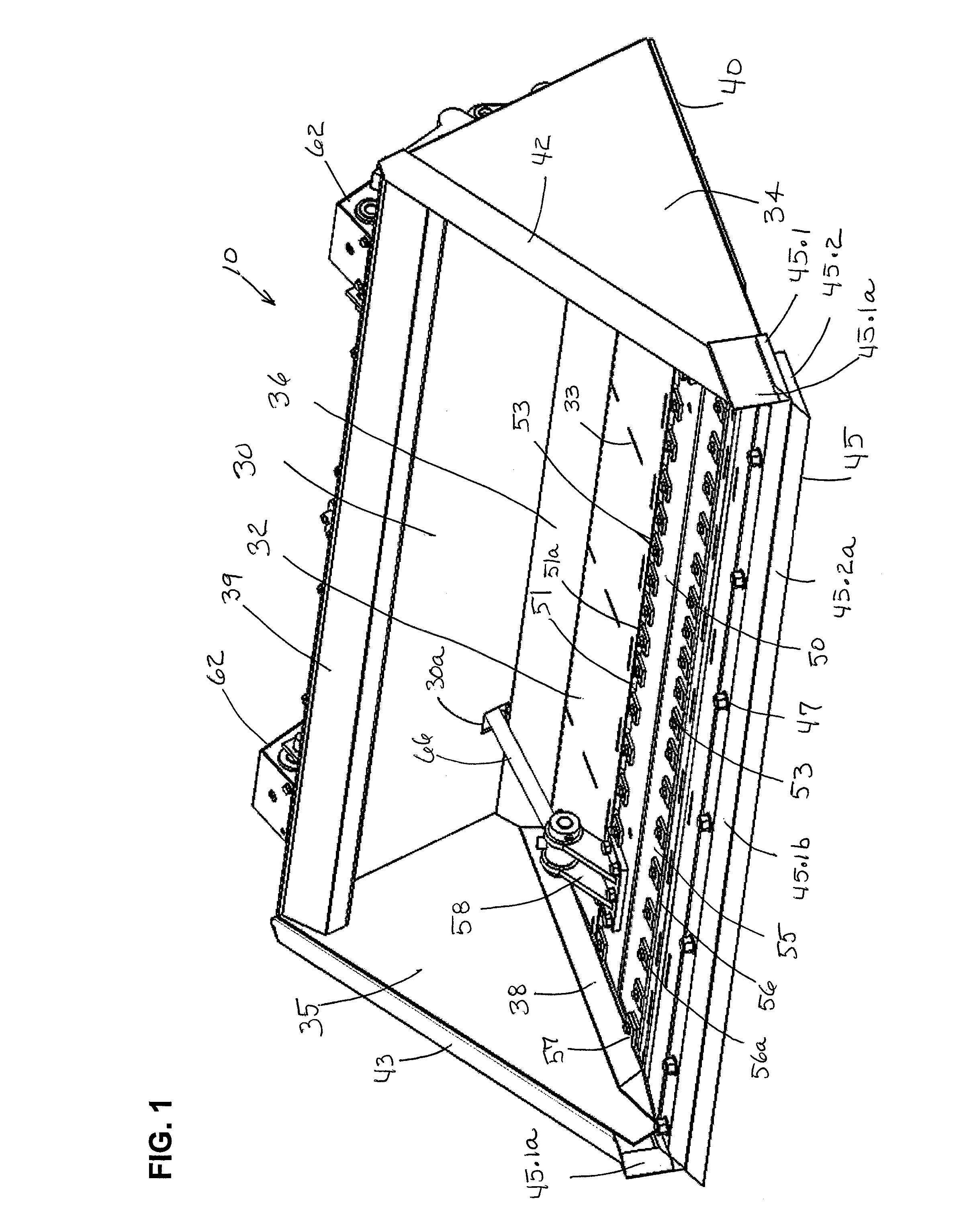
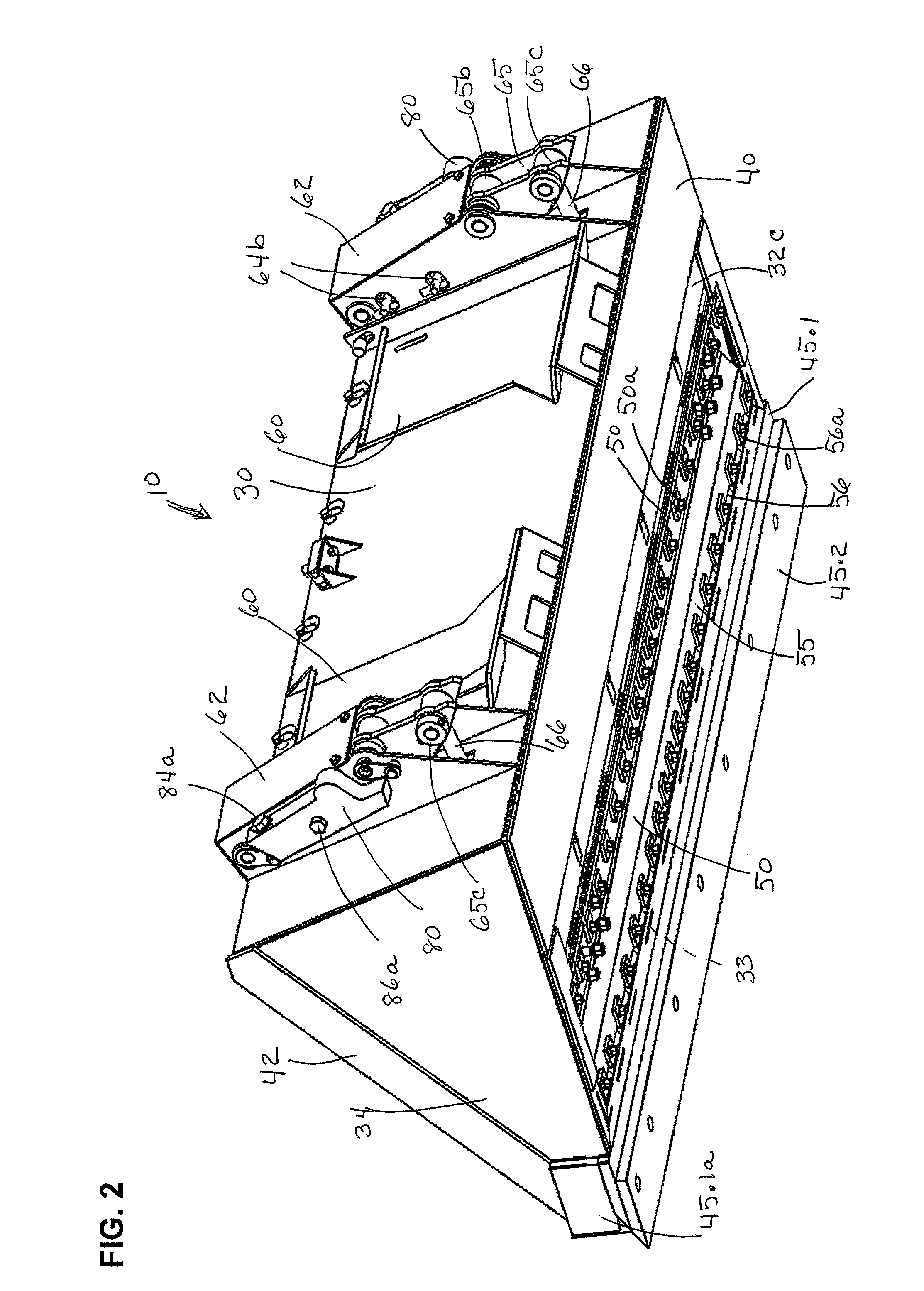
[0043]The below described preferred embodiments of bucket assemblies illustrate the general principles embodied in the invention. Such descriptions are not intended to be offered or used in any limiting manners, but only illustrate specific examples of bucket assemblies and portions thereof incorporating the broad principles of the invention. All alternatives and variations of the principles and features of the described embodiments are intended to be included within the broad scope of the claims appended hereto, whether such variations and alternatives are specifically addressed herein.

[0044]Referring to the Figures, a first embodiment of a bucket assembly incorporating the principles of this invention is illustrated at 10. As used herein in describing the bucket assemblies of the preferred embodiments, the terms “bucket assembly” and “bucket” will be used interchangeably. The bucket assembly 10 of the first embodiment is generally of the type referred to as a front-end loading buc...


PUM


Abstract

An improved material handling bucket assembly is configured for construction or agricultural front loading or backhoe applications. Scraper and grader blades pivotally mounted relative to the bucket bottom cooperatively move to provide normal bucket operation, or scraping, or grading operations. A scraper blade selectively rotates between a first position closing an opening through the bottom wall of the bucket to a second position extending below the bucket for removing ground soil during a scraping operation and directing the removed soil into a collection chamber of the bucket. A single power source and linkage assembly controls movement of the scraper and grader blades, which also cooperatively move to change the size of the opening in the bottom wall during a scraping operation.

Description

FIELD OF THE INVENTION[0001]This invention relates generally to the field of construction or earth working equipment, and more specifically to an improved material handling bucket for use with such equipment as, for example, skid loaders, backhoes, pay loaders, farm tractors and other types of earth working construction or agricultural equipment in which a bucket is moved and / or manipulated by the equipment to perform grading, scraping, digging, or the like.BACKGROUND OF THE INVENTION[0002]The present invention applies to any type of earth working or material handling bucket of the type attached to and carried, moved and manipulated by a motive power source such as a vehicular piece of construction or agricultural equipment, in contrast to wheeled earth scraper apparatus that are pulled or pushed in trailer fashion over the earth surface being worked. Such construction or agricultural equipment includes, but is not limited to loaders of the skid steered type as well as those having ...

Claims


Application Information

Patent Timeline
Patent Type & Authority Patents(United States)
IPC IPC(8): E02F3/40
CPCE02F3/962E02F3/404
Inventor TULIBASKI, BEN
Owner TULIBASKI BEN
Why Eureka
Try Eureka