Eureka AIR delivers breakthrough ideas for toughest innovation challenges, trusted by R&D personnel around the world.

Terminal connecting device for energy storage module

a technology of energy storage module and connecting device, which is applied in the direction of current conducting connection, cell component details, cell components, etc., can solve the problems of low vibration resistance or durability, inability to guarantee connection reliability, and bad influence on the system using the module or assembly, so as to ensure connection durability and connection reliability, improve the structure, and increase the coupling strength

Active Publication Date: 2014-01-21
LS MATERIALS CO LTD
View PDF85 Cites 9 Cited by
  • Summary
  • Abstract
  • Description
  • Claims
  • Application Information

AI Technical Summary

Benefits of technology

[0019]The present invention is designed to solve the above problems, and therefore it is an object of the present invention to provide a terminal connecting device for an energy storage module that has improvements in the structure and a scheme for connecting a plurality of cells to be assembled to increase the coupling strength with cell terminals, thereby ensuring the connection durability and the connection reliability.
[0020]It is another object of the present invention to provide a terminal connecting device for an energy storage module that has improvements in the structure and a scheme for connecting a plurality of cells to be assembled to minimize the height and volume, thereby reducing the full size of the module or assembly.
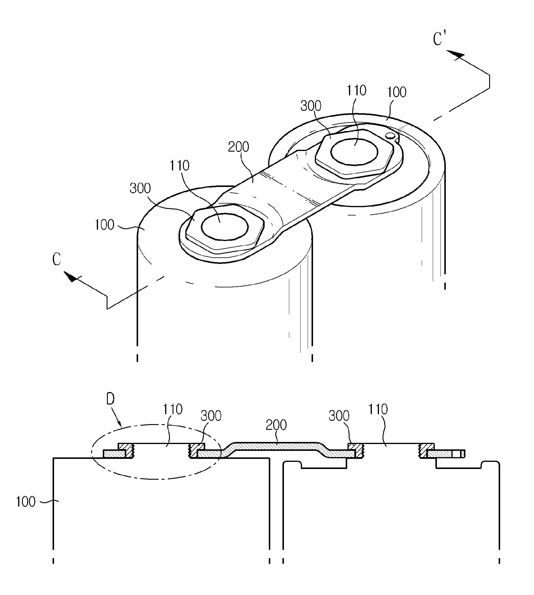
[0027]Preferably, the body portion of the busbar has a bent portion at the lower surface in the middle thereof to avoid the interference with a sleeve provided to provide insulation between the cells.

Problems solved by technology

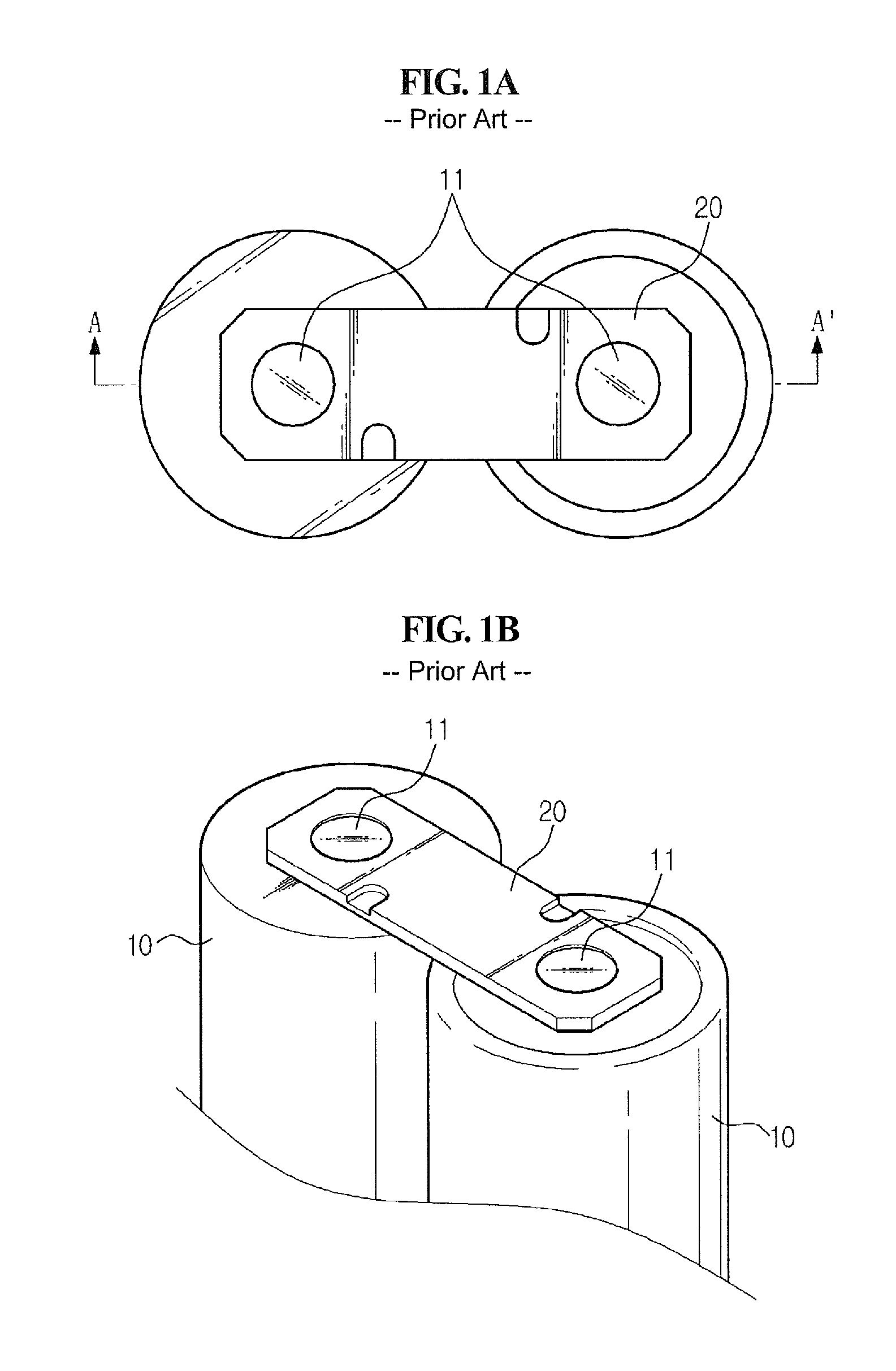
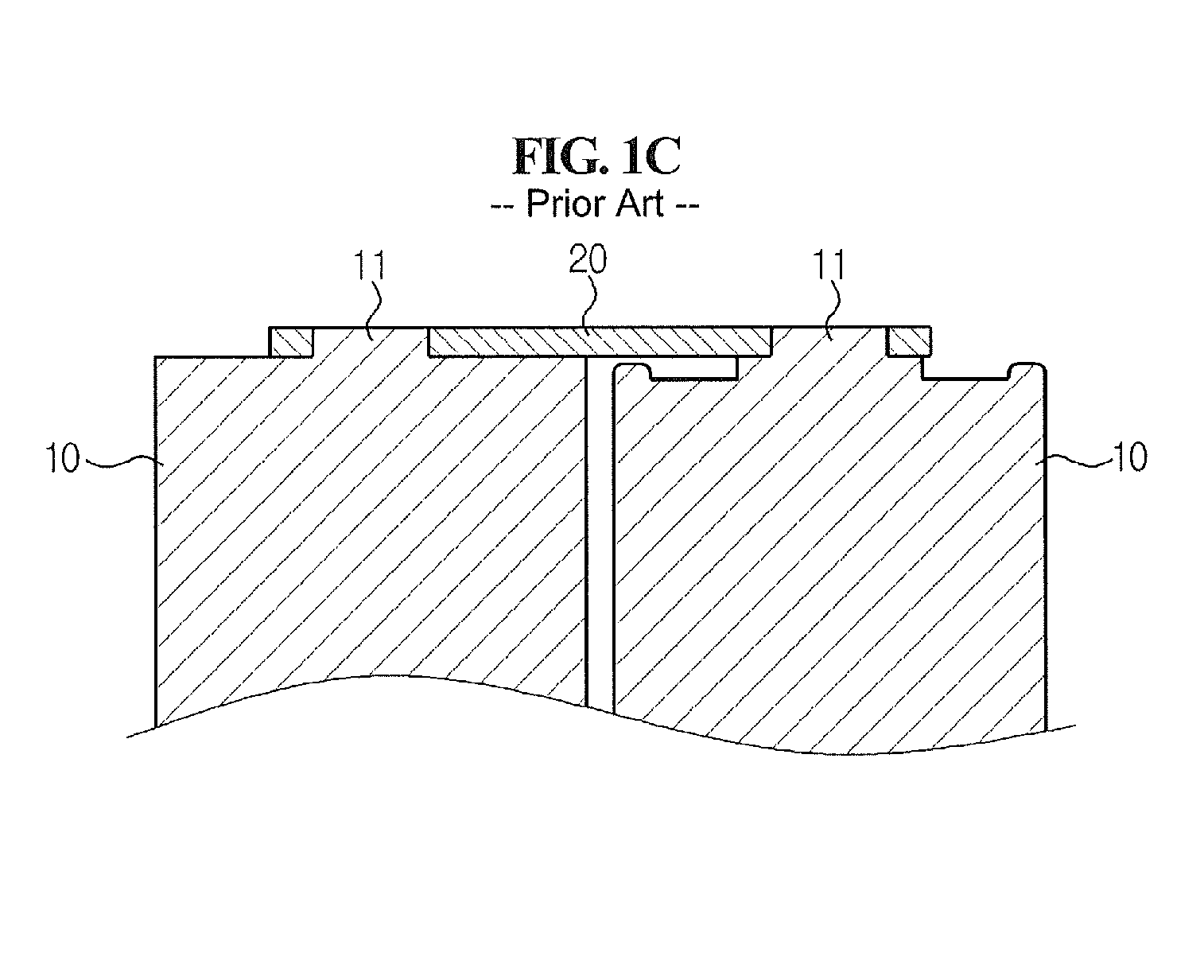
However, this connection by an interference fit using the conventional busbar 20 has advantages such as being simple in configuration, inexpensive costs, and easy to assemble, but cannot guarantee the connection reliability when the tightness of fit decreases.
That is, the vibration resistance or durability is low.
Moreover, when the fit becomes loose or the cell terminal 11 slips off, it will have a bad influence on a system using the module or assembly.
This is because it could lead to the possibility of fault occurrence increasing along with the difficulty in manufacturing the components.
Because of the problems above, this conventional connection does not go with the trend of equipments using an energy storage module or assembly toward minimization and light weight, and unnecessary height and volume has a bad influence on the design of the products.
That is, the freedom of the design reduces and the design of the products is restricted.

Method used


Image

  • Terminal connecting device for energy storage module
  • Terminal connecting device for energy storage module
  • Terminal connecting device for energy storage module

Examples


Embodiment Construction

[0048]The present invention will now be described in detail with reference to the accompanying drawings. Prior to description, it should be understood that terms and words used in the specification and the appended claims should not be construed as having common and dictionary meanings, but should be interpreted as having meanings and concepts corresponding to technical ideas of the present invention in view of the principle that the inventor can properly define the concepts of the terms and words in order to describe his / her own invention as best as possible. Accordingly, the description proposed herein is just a preferable example for the purpose of illustrations only, not intended to limit the scope of the invention, so it will be apparent to those skilled in the art that various modifications and variation can be made in the present invention without departing from the spirit or scope of the invention.

[0049]The present invention is characterized in that improvements are implemen...


PUM

PropertyMeasurementUnit
lengthaaaaaaaaaa
heightaaaaaaaaaa
cylindrical shapeaaaaaaaaaa

Abstract

Disclosed is a terminal connecting device for an energy storage module including a busbar having a body portion formed of a plate having a predetermined length stepped at both ends, and a cell terminal mounting portion having an insert hole at each end of the body portion, and a fastening member formed of a plate to secure the busbar by a screw connection with a cell terminal through the insert hole of the busbar, the fastening member having a nut body portion with a hollow at the center and the outer periphery processed in the shape of a nut, and a nut screw portion having a screw thread formed along the inner periphery of the hollow of the nut body portion, wherein the height of the step of the body portion of the busbar corresponds to the thickness of the nut body portion of the fastening member.

Description

CROSS-REFERENCE TO RELATED APPLICATION(S)[0001]This application claims priority from Korean Patent Application No. 10-2011-0130421, filed on Dec. 7, 2011, the entire disclosure of which is incorporated herein by reference for all purposes.BACKGROUND[0002]1. Field[0003]Exemplary embodiments relate to an energy storage device such as an ultracapacitor or battery, and more particularly, to a terminal connecting device for connecting a plurality of cells for a high voltage energy storage assembly.[0004]2. Description of the Related Art[0005]Generally, a representative example of an electrical energy storage device includes a battery and a capacitor.[0006]Among capacitors, an ultracapacitor, also known as a supercapacitor, is an energy storage device having characteristics in between those of an electrolytic condenser and a secondary battery. Since an ultracapacitor has high efficiency and a semipermanent life span, the ultracapacitor is considered as a next-generation energy storage dev...

Claims


Application Information

Patent Timeline
Patent Type & Authority Patents(United States)
IPC IPC(8): H01R4/38H01M50/505H01M50/559H01M50/569
CPCH01M2/204H01M2/20H01G9/004H01G9/26H01G9/008H01G11/76Y02E60/13H01G11/10H01M2/26H01M2/30Y02E60/10H01M50/559H01M50/505H01M50/569
Inventor LEE, JAE-KYUNGKWON, YOON-HYEOKSUH, TAE-HO
Owner LS MATERIALS CO LTD
Why Eureka
Eureka Blog
Learn More