Vibration actuator and method for manufacturing the same

a technology of vibration actuator and actuator, which is applied in the direction of piezoelectric/electrostrictive/magnetostrictive devices, piezoelectric/electrostriction/magnetostriction machines, electrostatic motors, etc., can solve the problems of generating abnormal noise, reducing the stability of relative movement, and affecting the stability of projections, etc., to achieve stable spring stiffness and easy manufacturing

Active Publication Date: 2014-01-21
CANON KK
View PDF10 Cites 7 Cited by
  • Summary
  • Abstract
  • Description
  • Claims
  • Application Information

AI Technical Summary

Benefits of technology

[0008]The present invention provides a vibration actuator which has a stable spring stiffness and which can be easily manufactured. The present invention also provides a method for manufacturing the vibration actuator.
[0010]According to the present invention, a vibration actuator which has a stable spring stiffness and which can be easily manufactured and a method for manufacturing the vibration actuator are provided.

Problems solved by technology

Accordingly, there is a possibility that an abnormal noise will be generated as the driven member hops in response to the vibration of the vibrator.
In addition, there is also a possibility that the stability of the relative movement will be reduced.
However, this structure has the following problem.
That is, since the projections are provided as separate components and are bonded to the planar elastic member, there is a risk that the projections will be slightly displaced.
As a result, there is a possibility that the desired spring stiffness cannot be obtained or the desired performance cannot be achieved by the actuator.
In addition, since the number of manufacturing steps is increased, high costs are incurred.

Method used


Image

  • Vibration actuator and method for manufacturing the same
  • Vibration actuator and method for manufacturing the same
  • Vibration actuator and method for manufacturing the same

Examples


first embodiment

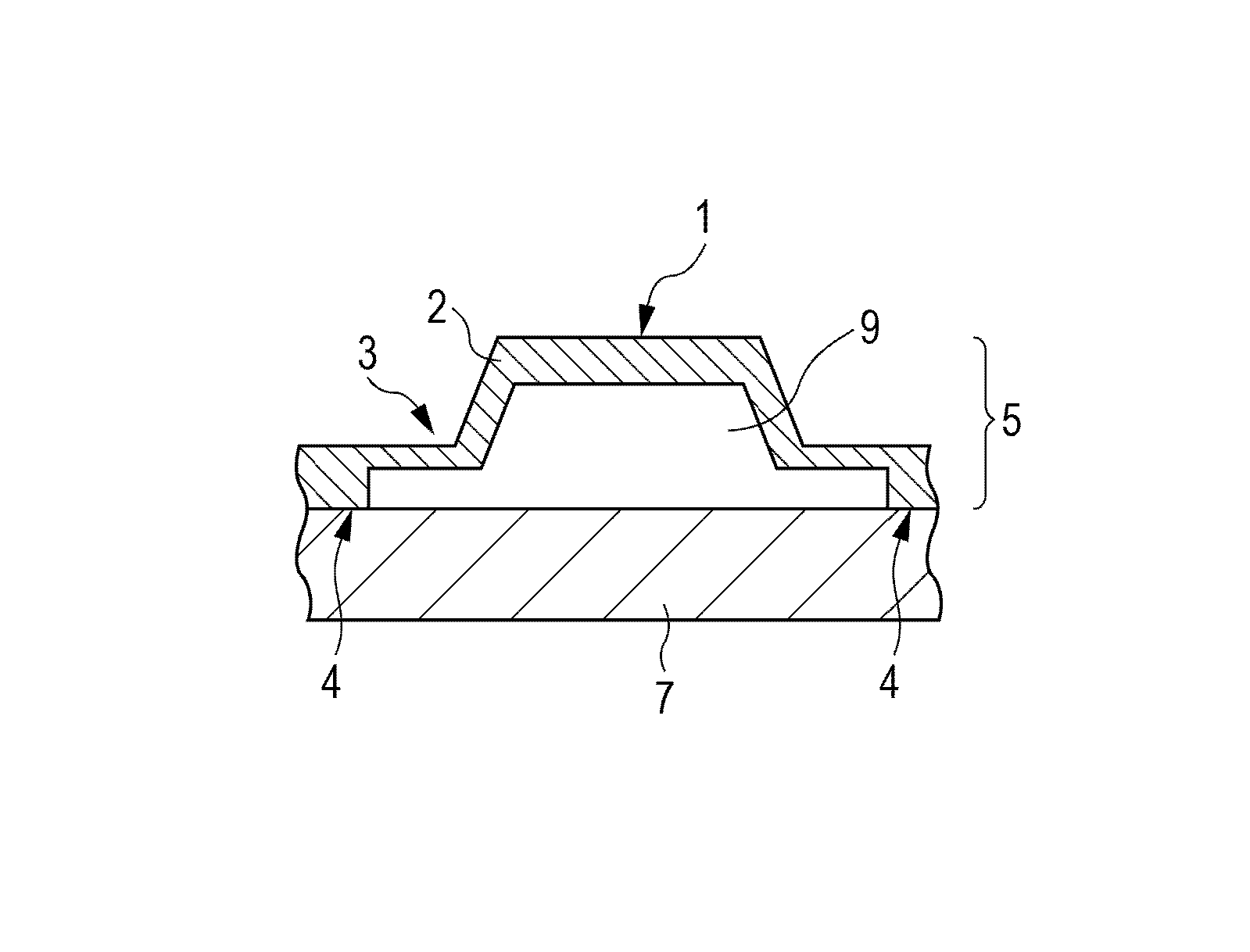
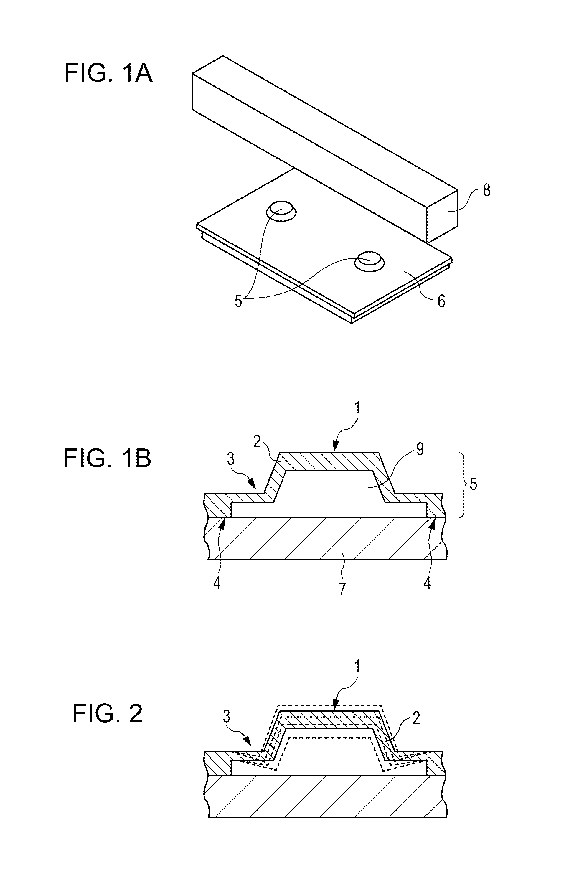
[0026]The structure of a vibration actuator according to a first embodiment of the present invention will be described with reference to FIGS. 1A and 1B. FIG. 1A is a perspective view of the vibration actuator according to the present embodiment, and FIG. 1B is a sectional view of a single projection. As illustrated in FIG. 1A, the vibration actuator according to the present embodiment includes a vibrating body including projections 5 and an elastic body 6 and a driven member 8. As illustrated in FIG. 1B, each projection 5 includes a contact portion 1 between the elastic body 6 and the driven member 8, a spring portion 3 that reduces the vibration stiffness of the vibrating body in the direction in which a pressure is applied, and a standing portion 2 that connects the contact portion 1 and the spring portion 3 to each other. The elastic body 6 includes bonding portions 4 between the projections 5 and an electromechanical conversion device 7.

[0027]The elastic body 6 is formed integr...

second embodiment

[0029]The structure of a vibration actuator according to a second embodiment of the present invention will be described with reference to FIGS. 4A and 4B. FIG. 4A is a perspective view of the vibration actuator according to the present embodiment, and FIG. 4B is a sectional view of a single projection. As illustrated in FIG. 4A, the vibration actuator according to the present embodiment includes a vibrating body including projections 5, an elastic body 6, and a plurality of holes 10 formed in the elastic body 6 and a driven member 8. As illustrated in FIG. 4B, each projection 5 includes a contact portion 1 between the elastic body 6 and the driven member 8, a standing portion 2 that connects the contact portion 1 and an electromechanical conversion device 7 to each other, and the holes 10 formed in the standing portion 2. Although four holes 10 are formed in the present embodiment, the number of holes is not limited as long as the number is 1 or more. The shape of the holes 10 may b...

third embodiment

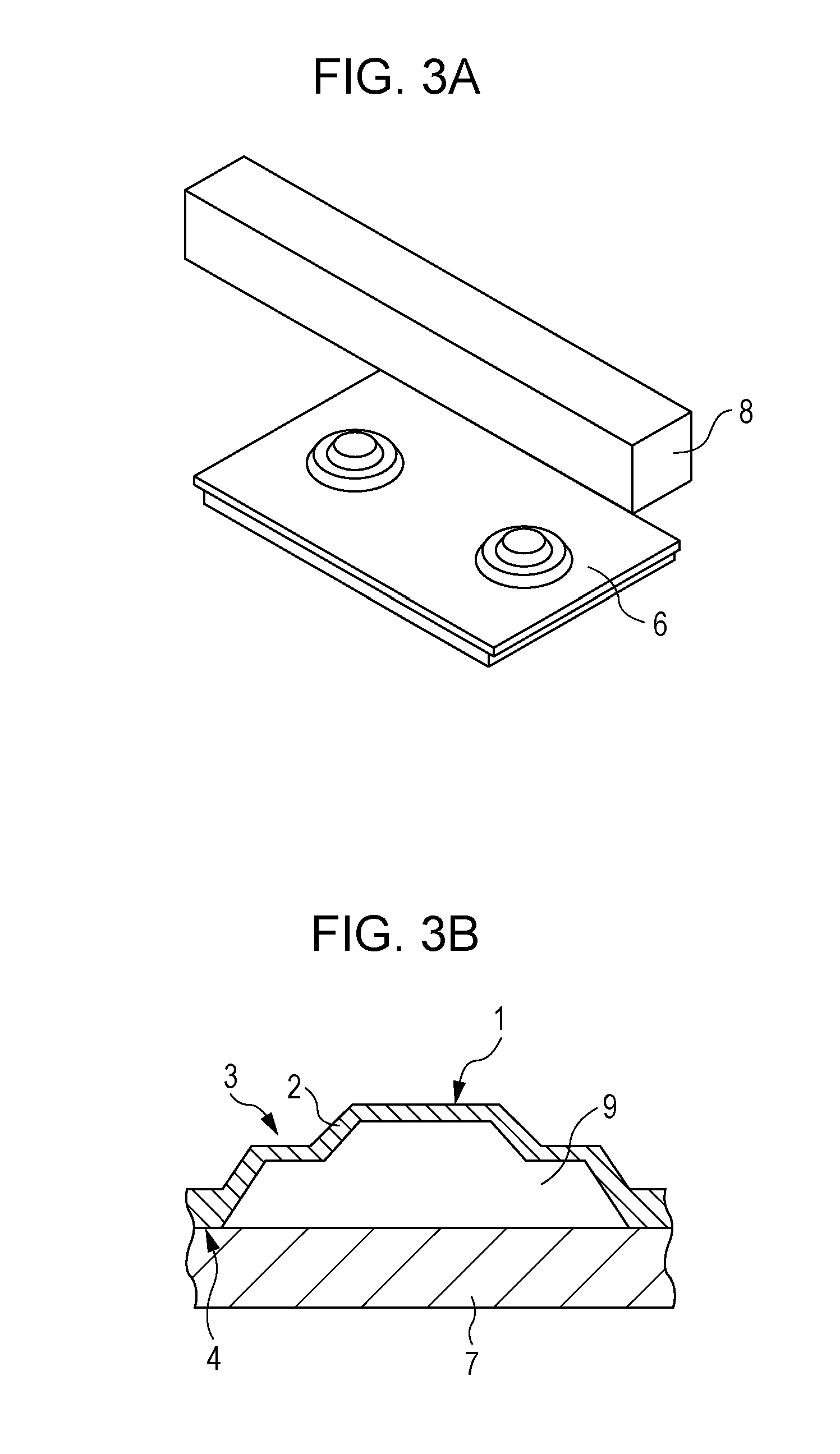
[0031]The structure of a vibration actuator according to a third embodiment of the present invention will be described with reference to FIGS. 6A and 6B. FIG. 6A is a perspective view of the vibration actuator according to the present embodiment, and FIG. 6B is a sectional view of a single projection. Referring to FIG. 6A, the vibration actuator includes a vibrating body including projections 5 and an elastic body 6 and a driven member 8. The vibrating body is provided with elongate holes 11 that receive excess portions generated during press working. As illustrated in FIG. 6B, in the vibration actuator according to the present embodiment, each projection 5 includes a contact portion 1 between the elastic body 6 and the driven member 8, a spring portion 3 that reduces the vibration stiffness of the vibrating body in the direction in which a pressure is applied, and a standing portion 2 that connects the contact portion 1 and the spring portion 3 to each other. The elastic body 6 inc...


PUM

PropertyMeasurementUnit
thicknessaaaaaaaaaa
thicknessesaaaaaaaaaa
elasticaaaaaaaaaa

Abstract

A vibration actuator includes an elastic body on which at least one projection is formed and a vibrating body including an electromechanical conversion device, and drives a driven member that is in contact with a contact portion of the projection by causing an end portion of the projection to perform an ellipsoidal movement in response to a combination of two vibration modes generated in the vibrating body when an alternating driving voltage is applied. The elastic body is formed integrally with the projection and a bonding portion between the projection and the electromechanical conversion device. A space is provided between the contact portion and the electromechanical conversion device to which the projection is bonded. The spring portion is provided between the bonding portion and the contact portion and causes the projection to exhibit a spring characteristic when the contact portion is pressed by the driven member.

Description

BACKGROUND OF THE INVENTION[0001]1. Field of the Invention[0002]The present invention relates to vibration actuators and methods for manufacturing the vibration actuators. More particularly, the present invention relates to a vibration actuator including a substantially rectangular planar vibrator having a projection that serves as a friction member on one side thereof and a method for manufacturing the vibration actuator.[0003]2. Description of the Related Art[0004]Various vibration actuators that linearly drive driven members have been proposed. For example, U.S. Pat. No. 7,109,639 proposes a vibration-type driving apparatus. The driving principle of the apparatus will be described with reference to FIGS. 11, 12A, and 12B. Referring to FIG. 11, a vibrator 106 is provided with an electromechanical conversion device 107 bonded thereto. FIGS. 12A and 12B illustrate two bending vibration modes of the piezoelectric vibrator. The vibration mode illustrated in FIG. 12A is one of the two ...

Claims


Application Information

Patent Timeline
Patent Type & Authority Patents(United States)
IPC IPC(8): H02N11/00
CPCH02N2/001H02N2/005Y10T29/49Y10T29/42H01L41/35H02N2/0055H02N2/006H02N2/0065H02N1/008H02N2/12H02N2/163H02N2/16H02N2/22H10N30/09H10N30/05H10N30/071
Inventor ODA, YUKIYAMAMOTO, SHINJIATSUTA, AKIO
Owner CANON KK
Why Eureka
Try Eureka