Supporting temporary barriers

a temporary barrier and support technology, applied in the direction of traffic signals, applications, roads, etc., can solve the problem of pedestrians with a significant risk of tripping, and achieve the effect of reducing the danger of pedestrian tripping, low profile and low profil

Active Publication Date: 2016-07-07
OXFORD PLASTIC SYST
View PDF10 Cites 6 Cited by
  • Summary
  • Abstract
  • Description
  • Claims
  • Application Information

AI Technical Summary

Benefits of technology

[0009]The use of the stiffening member, provides stiffness to the elongate stabilizing members and means that the profile of the stabilizing members can be kept low so as to reduce the danger of a pedestrian tripping over a foot of the base. In preferred embodiments, therefore, each stabilizing member is of low profile. By low profile is meant that the height of the stabilizing members over major parts of their respective lengths is below a height that would provide a significant risk of tripping for a pedestrian. In accordance with some embodiments of the invention, the height of the stabilizing members over major parts of their respective lengths does not exceed about 40 mm However, in some preferred embodiments of the invent

Problems solved by technology

By low profile is meant that the height of the stabilizing members over major parts of their respe

Method used


Image

  • Supporting temporary barriers
  • Supporting temporary barriers
  • Supporting temporary barriers

Examples


Embodiment Construction

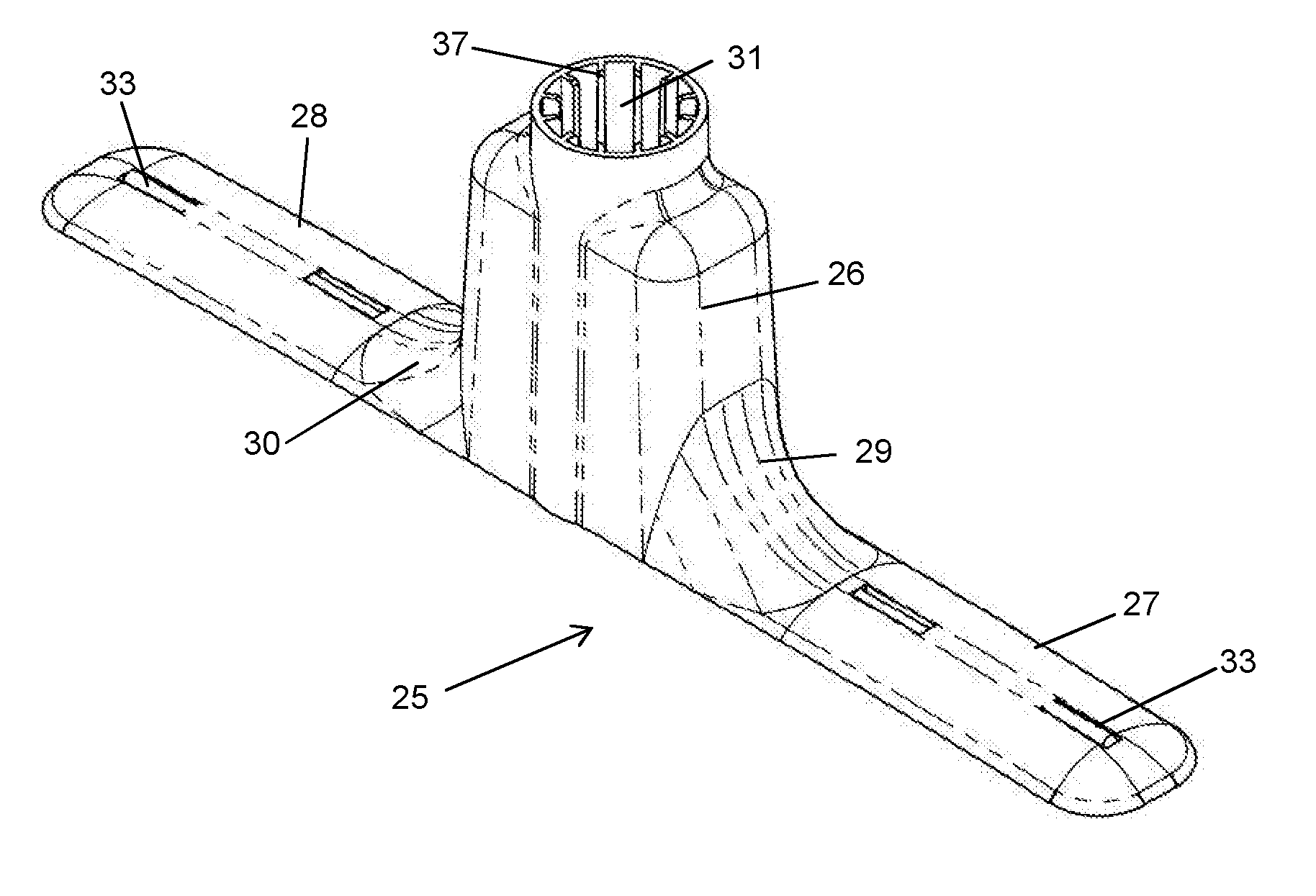
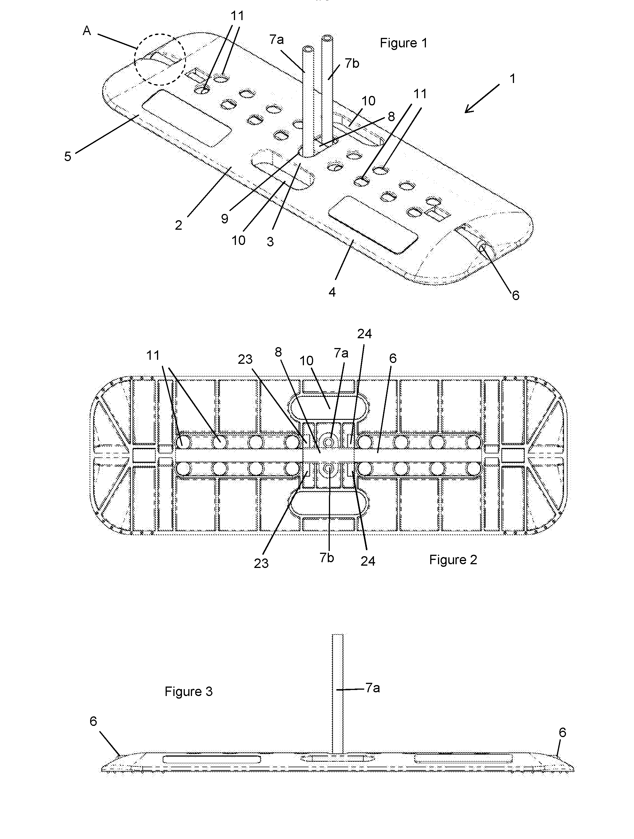
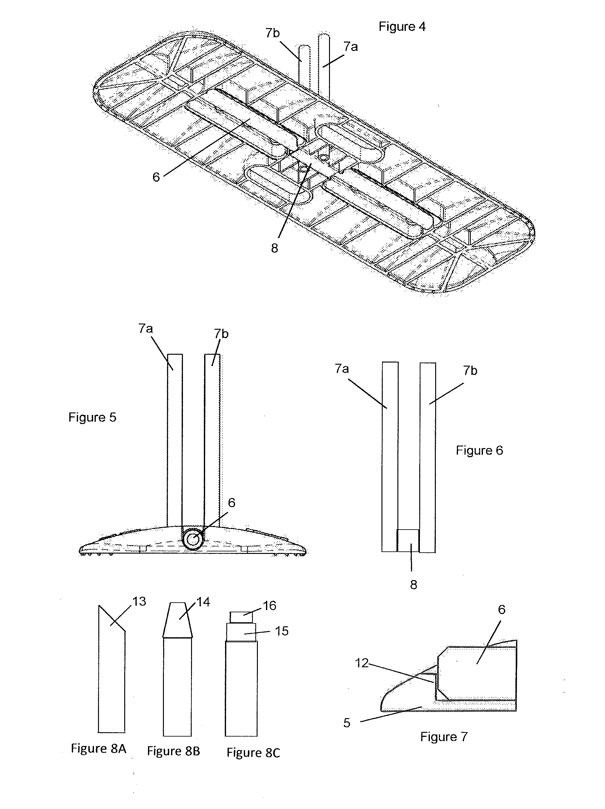
[0060]Referring now in detail to the Figures, in FIGS. 1 to 7 there is shown a base 1 for receiving fence poles. This base comprises a molded part 2 of plastics, defining an integrally formed central support member 3, first stabilizing member 4 and second stabilizing member 5. The base 1 further comprises a stiffening rod 6 and a pair of metal spigots 7a and 7b projecting up from the support member. The metal spigots are connected, e.g. by welding to a hollow box section 8 and project upwardly through an aperture 9 in the support member. The stiffening rod 6 passes through and is connected to the stabilizing members 4 and 5 and passes through the hollow box section 8. The stiffening rod passes continuously from adjacent the free end of stabilizing member 4 to adjacent the free end of stabilizing member 5. The free end of FIG. 6 shows the metalwork used, comprising the spigots 7a, 7b welded to the box section 8.

[0061]The rod 6 is of fiber reinforced resin, manufactured by pultrusion....


PUM


Abstract

A base for a temporary barrier has a spigot or socket to receive a fencing pole or to cooperate with a plastics fencing panel. The base has a support portion of plastics material on which is provided the spigot or socket. A pair of stabilizing members of plastics material of low profile extending in opposite directions from the support portion. A stiffening member is connected to each stabilizing member and extends horizontally from adjacent the remote end of one stabilizing member to adjacent the remote end of the other stabilizing member. In one form a pair of metal tubes extend upwardly and are connected to a hollow metal portion through which the stiffening member passes. In another form, a plastics portion projects upwardly and defines a socket.

Description

[0001]This application is entitled to the benefit of, and incorporates by reference essential subject matter disclosed in PCT Application No. PCT / GB14 / 52665 filed on Sep. 4, 2014, which claims priority to Great Britain Application No. 1315822.5 filed Sep. 5, 2013 and Great Britain Application No. 1402162.0 filed Feb. 7, 2014, which applications are hereby incorporated by reference.BACKGROUND OF THE INVENTION[0002]1. Technical Field[0003]This invention relates to a base for supporting a temporary barrier.[0004]2. Background Information[0005]In some case, a temporary barrier such as a fence may be provided with support posts, and a base for supporting a post may have a socket for receiving an end portion of a support post. Alternatively, if an end part of the fence support post is hollow and open ended—for example the support post is in the four of a tube—the base may have a spigot which is received within the end part of the support post. Other barriers such as panels of plastics mat...

Claims


Application Information

Patent Timeline
IPC IPC(8): E04H12/22E04H17/22
CPCE04H12/2269E04H17/22E04H12/2238E04H12/2261E01F9/692E04H17/009E04H12/22
Inventor WHITELEY, CHRISTOPHER
Owner OXFORD PLASTIC SYST
Why Eureka
Try Eureka