Touch screen overlay for visually impaired persons

a technology for visually impaired people and touch screen overlays, applied in the direction of transmission systems, instruments, electric digital data processing, etc., can solve the problems of many of the conventional means for accessing features on such devices or appliances for visually impaired such as magnifiers or voice command interfaces, and create complexity, so as to reduce work results and less complexity

a technology for visually impaired people and touch screen overlays, applied in the direction of transmission systems, instruments, electric digital data processing, etc., can solve the problems of many of the conventional means for accessing features on such devices or appliances for visually impaired such as magnifiers or voice command interfaces, and create complexity, so as to reduce work results and less complexity

US8633907B2Inactive Publication Date: 2014-01-21MAHALINGAM PADMANABHAN

Image

  • Touch screen overlay for visually impaired persons
  • Touch screen overlay for visually impaired persons
  • Touch screen overlay for visually impaired persons

Examples


Embodiment Construction

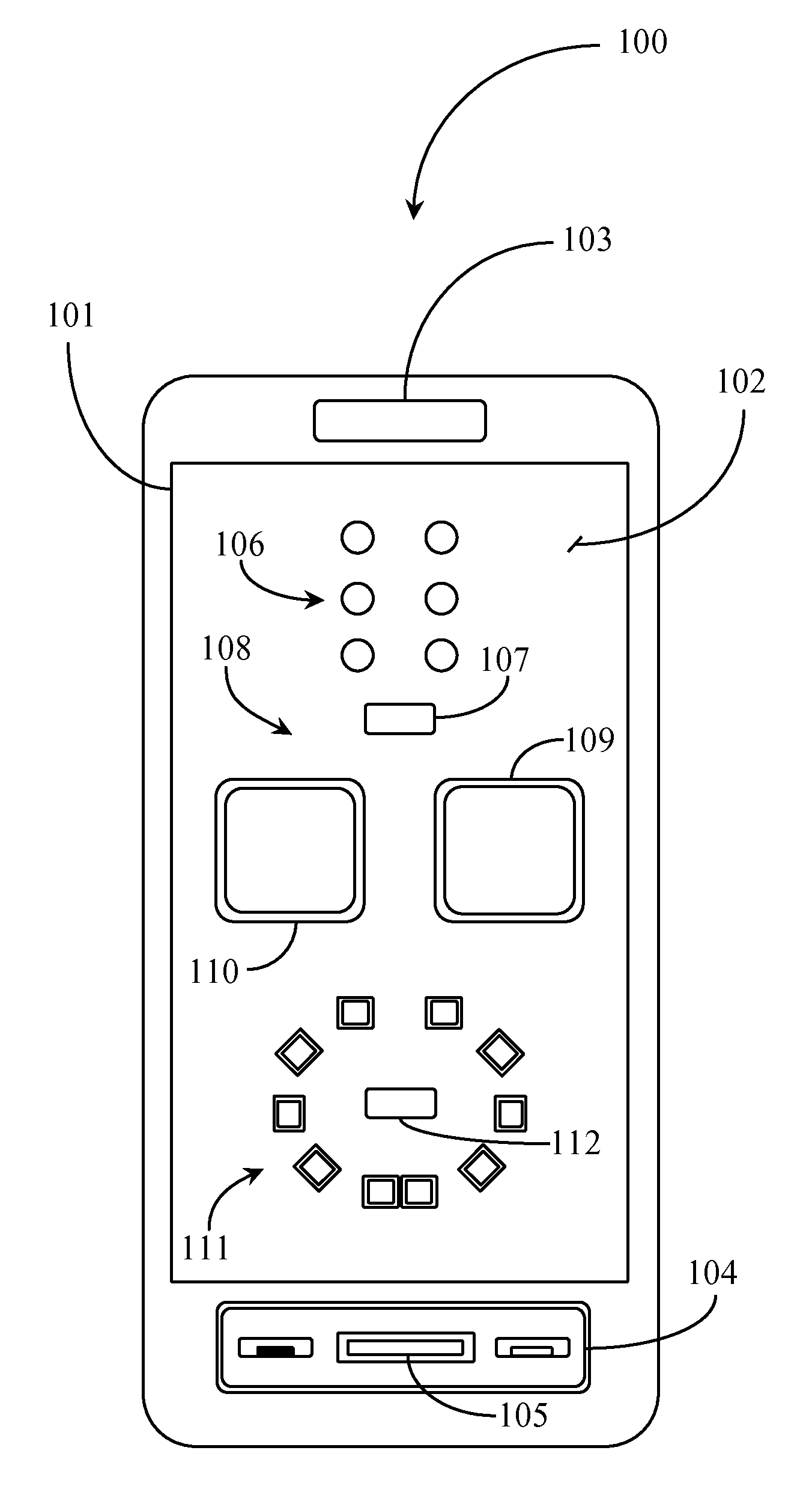
[0023]The inventor provides unique touch screen overlays and software for enabling a touch screen interface that may be used by a visually impaired person to send a message using one of a variety of alphanumeric techniques. The methods and apparatus of the present invention are described in enabling detail using the following examples, which may illustrate more than one embodiment of the present invention.

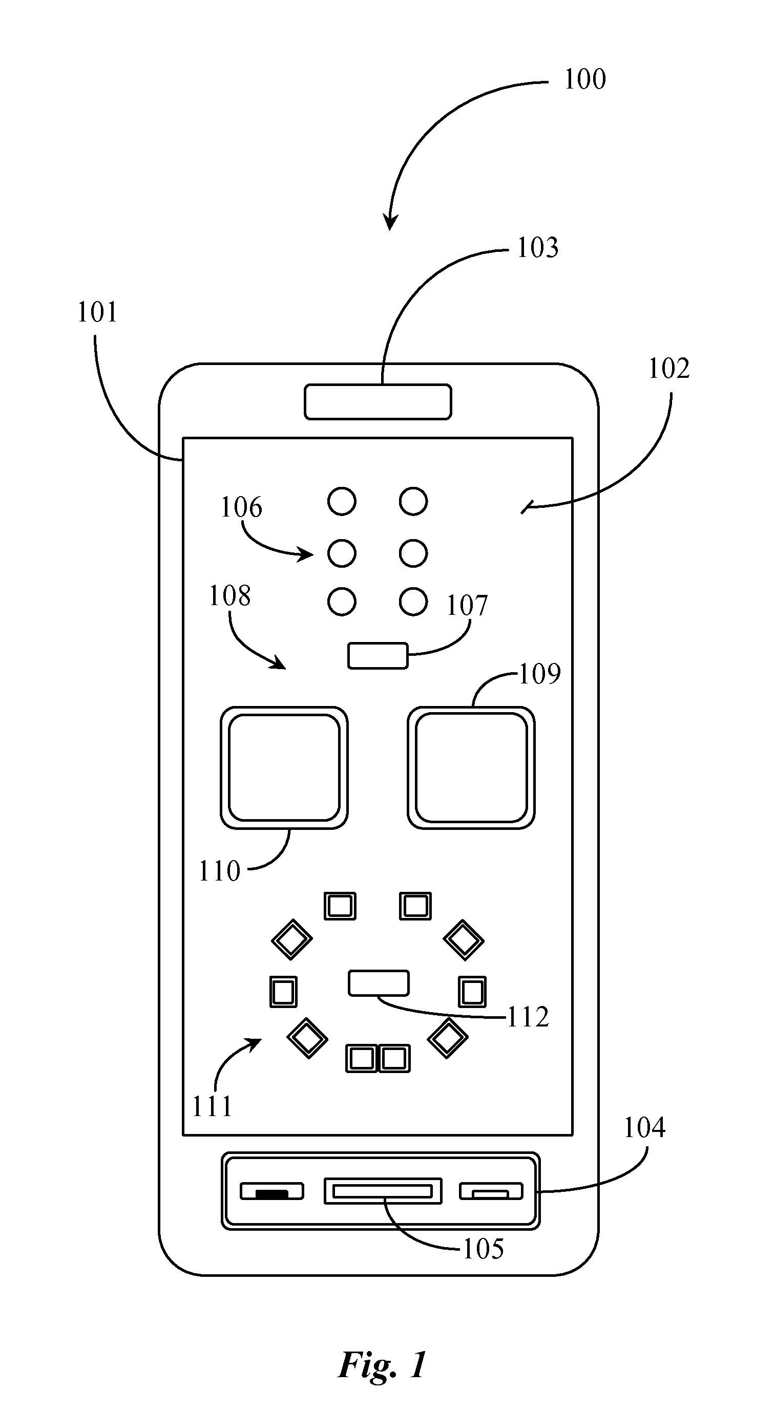
[0024]FIG. 1 is an elevation view of a communications appliance 100 supporting a touch screen interface 101 according to an embodiment of the present invention. Communication appliance 100 is a cellular telephone or “smartphone” in this embodiment. Smartphone 100 includes a touch screen 101 that is adapted to display information and to accept user input through use of a stylus or a user's fingers. In one embodiment touch screen 101 uses capacitive technology to sense a touch. In another embodiment touch screen 101 uses resistive technology to sense pressure from a touch. Smartphone...


PUM


Abstract

A touch screen overlay includes a flexible, substantially planar portion having length and width dimensions corresponding to a touch screen of an electronics appliance, one or more features for aligning the substantially planar portion with the touch screen, and a pattern of raised features and / or openings, providing facility for a person to interact with individual features or openings by touch rather than be sight.

Description

BACKGROUND OF THE INVENTION[0001]1. Field of the Invention[0002]The present invention is in the field of electronic input devices for computing appliances and pertains particularly to methods and apparatus for inputting information through the use of a touch screen.[0003]2. Discussion of the State of the Art[0004]In the field of electronic input devices for computing appliances, touch screens have evolved to become a primary input device for some computing and communications appliances. A touch screen uses capacitive or resistive methods to enable a user to touch a graphic or link displayed on the screen to interact with that graphic or link according to one or more interaction rules.[0005]Touch screens are becoming a common primary input device for third and fourth generation cellular telephones, personal digital assistants (PDAs), music players, such as iPods, and in some cases Laptop computers. In applications where the touch screen is the primary input device, the touch capabili...

Claims


Application Information

Patent Timeline
21 Jan 2014
Publication
US8633907B2
IPC
G06F3/041
CPC
G06F2203/04809; G09B21/003; G06F3/04886
Inventors
MAHALINGAM, PADMANABHAN