
Audio processing device

a processing device and audio technology, applied in the direction of transducer details, instruments, speech analysis, etc., can solve the problems of unnatural audio sound and unnatural directionality change with respect to the zoom value, and achieve the effect of indirect sound

Inactive Publication Date: 2014-01-21
YAMAHA CORP
View PDF16 Cites 1 Cited by
  • Summary
  • Abstract
  • Description
  • Claims
  • Application Information

AI Technical Summary

Benefits of technology

The invention relates to an audio processing device that can adjust the sound pressure level of a target sound component in a way that changes the sound receiving characteristics perceived by the listener. The device uses a component separation part to separate the target sound component from other non-target sound components, and adjusts the sound pressure level of each component separately. The device also adjusts the sound pressure level of the target sound component based on a zoom value that can be adjusted by the user. This allows for a natural change in sound receiving characteristics as the distance between the listener and the target changes. The device can be used in a variety of acoustic spaces and provides a more immersive listening experience.

Problems solved by technology

However, in the configuration in which the directionality is changed stepwise, the audio sound sounds unnatural since the acoustic characteristics change discontinuously according to the zoom value.
However, there is problem in that directionality changes unnaturally with respect to the zoom value since the relationship between the directionality and the zoom value is different from the relationship between acoustic characteristics heard in an actual acoustic space and the distance to the sound source.

Method used


Image

  • Audio processing device
  • Audio processing device
  • Audio processing device

Examples


first embodiment

B: First Embodiment

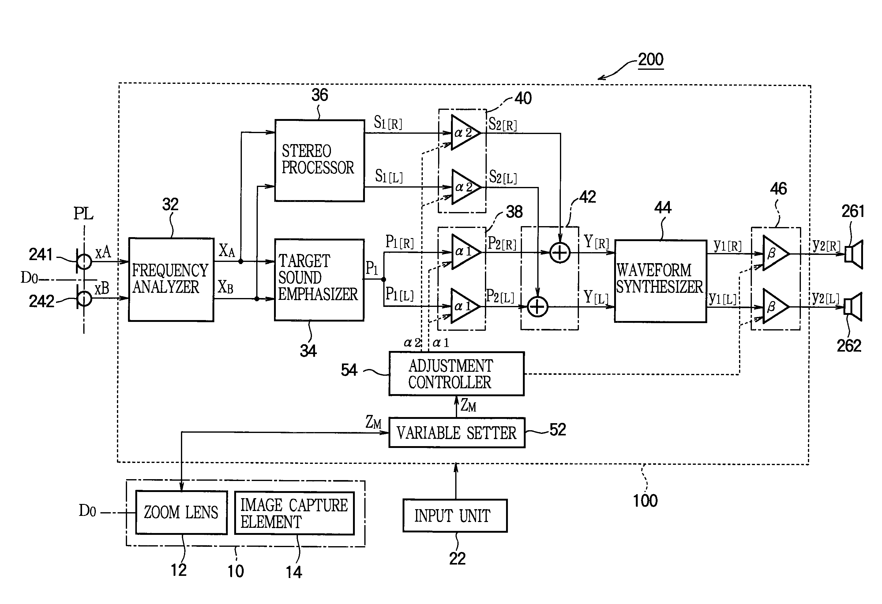
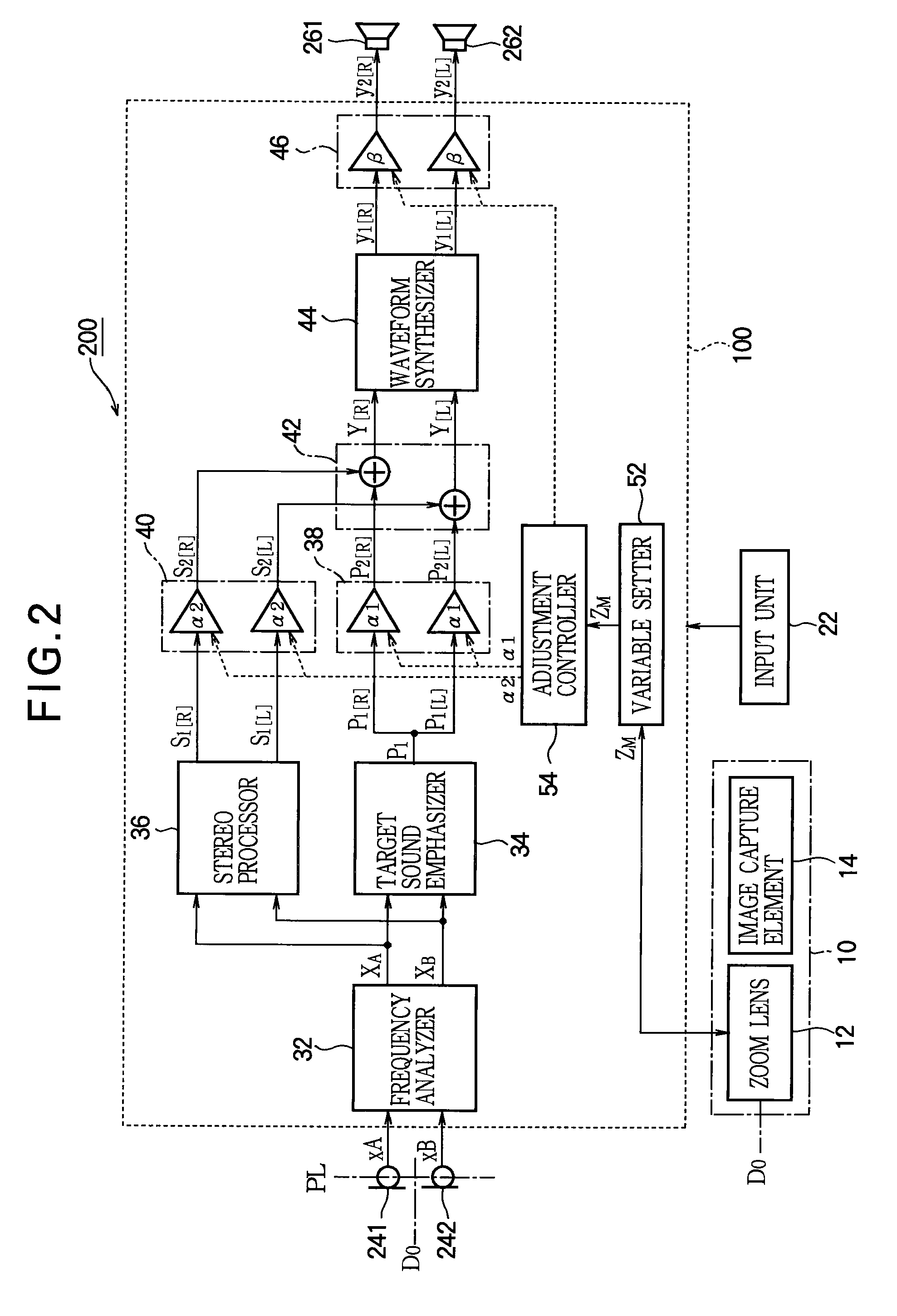
[0035]FIG. 2 is a block diagram of an image capture device 200 using an audio processing device 100 according to a first embodiment of the invention. The image capture device 200 is a video camera that captures a moving image and receives sound and stores the moving image and sound in a recording medium. As shown in FIG. 2, the image capture device 200 includes an image capture processor 10, an input unit 22, a plurality of sound receiving devices 241 and 242 such as microphones, the audio processing device 100, and a plurality of sound emission devices 261 and 262.

[0036]The image capture processor 10 captures and stores a moving image. Specifically, the image capture processor 10 includes an image capture element 14 that generates image data according to incident light and a zoom lens 12 that forms an image of an object or target focused on the surface of the image capture element 14 according to the variable focal distance. The input unit 22 includes manipulator...

second embodiment

C: Second Embodiment

[0058]Next, a second embodiment of the invention is described as follows. The second embodiment is a specific example of the target sound emphasizer 34. In each example described below, elements having the same operations and functions as those of the first embodiment are denoted by the same reference numerals as described above and detailed descriptions thereof are omitted as appropriate.

[0059]FIG. 6 is a block diagram of the target sound emphasizer 34 in the second embodiment. As shown in FIG. 6, the target sound emphasizer 34 includes a component separator (component separation part) 72, a third adjuster (third adjustment part) 74, a fourth adjuster (fourth adjustment part) 76, a fluctuating sound suppressor 78, and a mixer (second mixing part) 80. The component separator 72 generates target sound components QA1 in which a target sound is dominant and non-target sound components QB1 in which a non-target sound is dominant from an audio signal XA and an audio s...

third embodiment

D: Third Embodiment

[0083]FIG. 10 is a block diagram of an audio processing device 100 according to a third embodiment of the invention. As shown in FIG. 10, the audio processing device 100 of the third embodiment is constructed by adding a room constant setting part in the form of a room constant setter 56 to the audio processing device 100 of the first embodiment. The room constant setter 56 variably sets a room constant R according to a user manipulation of the input unit 22.

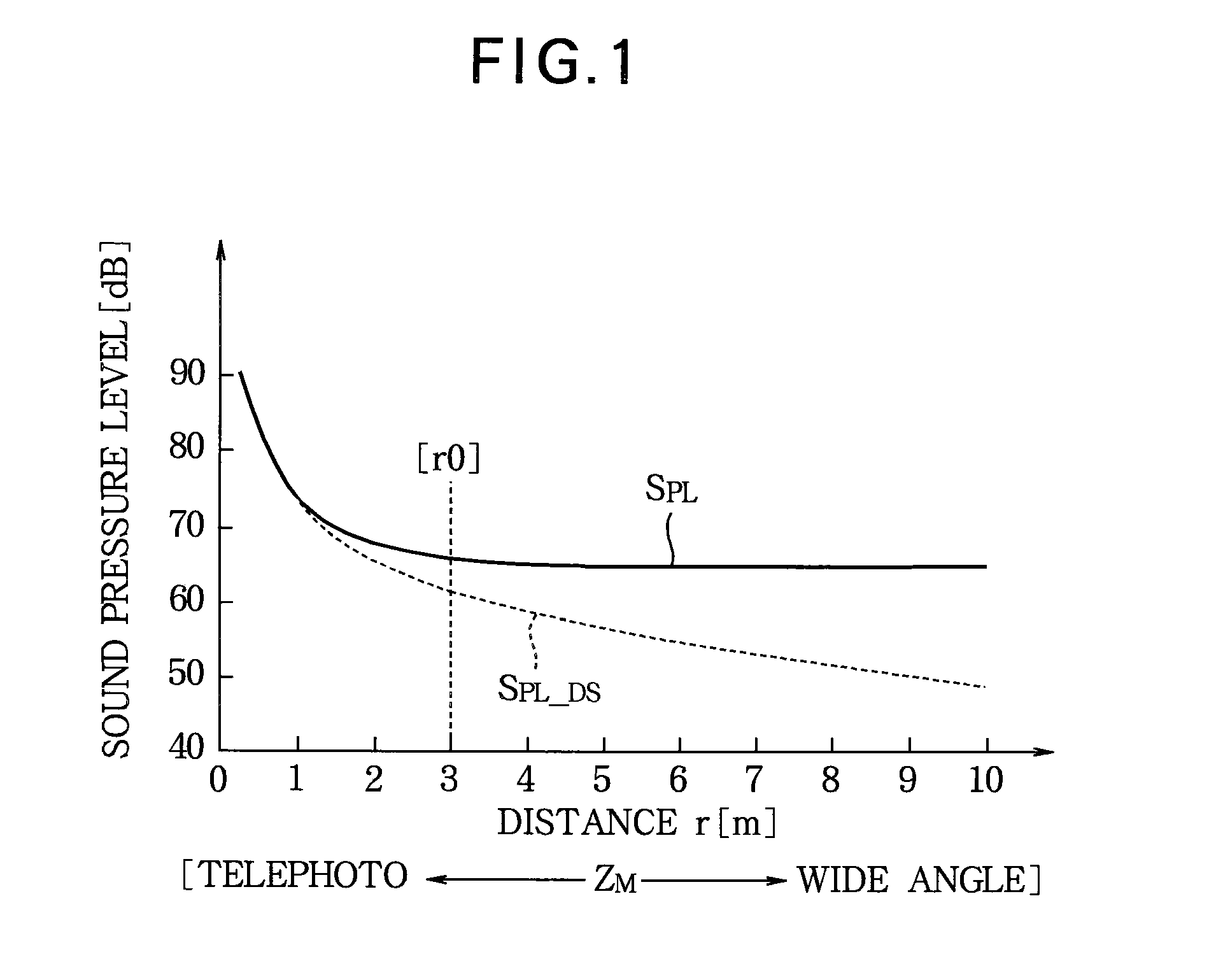
[0084]As can be understood from the above Equation (1), the ratio of the sound pressure level of the indirect sound to the sound pressure level of the direct sound tends to decrease as the room constant R increases (i.e., as the area S or the sound absorption coefficient α of the acoustic space increases). In the third embodiment, the adjustment controller 54 variably controls the adjustment values α1 to α4 according to the zoom value ZM and the room constant R so that such a tendency is reflected in changes o...


PUM


Abstract

In an audio processing device, a target sound emphasizer generates a target sound emphasized component by emphasizing a target sound component contained in a plurality of audio signals generated by a plurality of sound receiving devices. A stereo processor generates a stereo component of a plurality of channels from the plurality of audio signals. A first adjuster adjusts a sound pressure level of the target sound emphasized component according to a first adjustment value, and a second adjuster adjusts a sound pressure level of the stereo component according to a second adjustment value. A variable setter variably sets a zoom value which is changeable between a wide angle side and a telephoto side relative to a target. An adjustment controller controls the first adjustment value according to the zoom value such that the sound pressure level of the target sound emphasized component exponentially decreases as the zoom value changes toward the wide-angle side and controls the second adjustment value according to the zoom value such that the sound pressure level of the stereo component increases as the zoom value changes toward the wide-angle side.

Description

BACKGROUND OF THE INVENTION[0001]1. Technical Field of the Invention[0002]The present invention relates to a technology for variably controlling sound receiving characteristics such as directionality.[0003]2. Description of the Related Art[0004]For example, an audio zoom technology for changing sound receiving characteristics such as directionality according to a zoom value of a video camera has been suggested previously. Japanese Patent No. 3109938 discloses a configuration in which a coefficient defining directionality is changed stepwise or linearly according to the zoom value such that the directionality of received sound increases (i.e., as a sound-receiving angle decreases) as the zoom value approaches the telephoto side.[0005]However, in the configuration in which the directionality is changed stepwise, the audio sound sounds unnatural since the acoustic characteristics change discontinuously according to the zoom value. If the coefficient defining directionality is changed l...

Claims


Application Information

Patent Timeline
Patent Type & Authority Patents(United States)
IPC IPC(8): H04B1/06G10L21/0208G10L21/0232
CPCH04B1/06H04R1/406H04R3/005
Inventor KONDO, KAZUNOBUYAMAUCHI, KENICHIKEMMOCHI, HIDEKI
Owner YAMAHA CORP
Learn More