Lens with variable refraction power for the human eye

a technology of refraction power and human eye, which is applied in the field of human eye refraction power, can solve the problems of affecting the the eye is distracting, and the multi-focal glasses are unsuitable for many eyewearers, so as to achieve enhanced refraction power of the lens

Active Publication Date: 2014-01-28
BINDER HELMUT
View PDF8 Cites 39 Cited by
  • Summary
  • Abstract
  • Description
  • Claims
  • Application Information

AI Technical Summary

Problems solved by technology

However, the jump or break of vision in the middle of the glasses turns out to be distracting.
However, also multifocal glasses turn out to be unsuitable for many spectacle wearers.
However, these lenses have the same drawbacks as the multifocal glasses.
On the distance in between, the patient's focus is not perfect.
This, however, is not sufficient, since for example for the ability to read, an accommodation of higher than 3 dpt has to be realized.
Additionally, an exact positioning of the intraocular lens is difficult.

Method used


Image

  • Lens with variable refraction power for the human eye
  • Lens with variable refraction power for the human eye
  • Lens with variable refraction power for the human eye

Examples


first embodiment

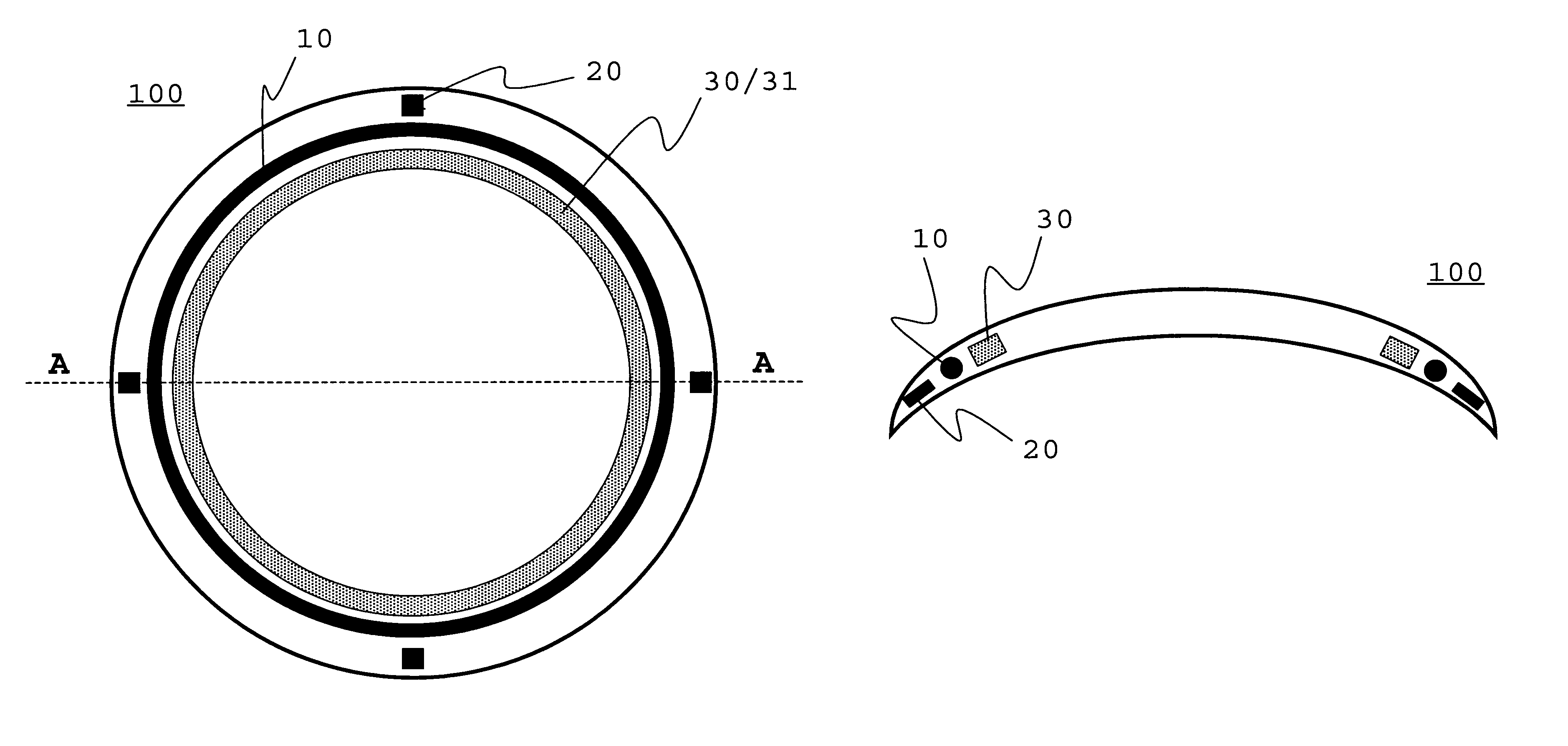
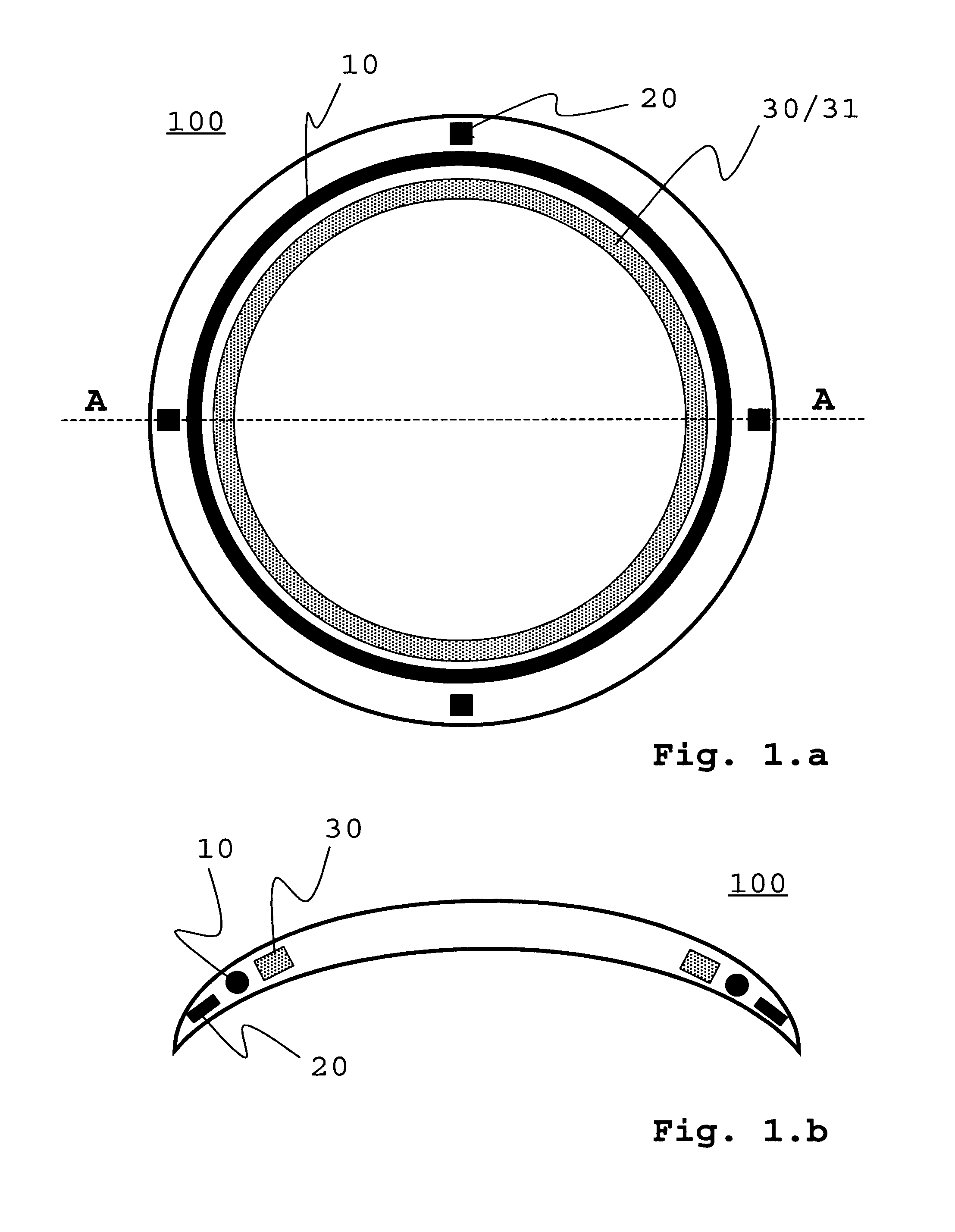
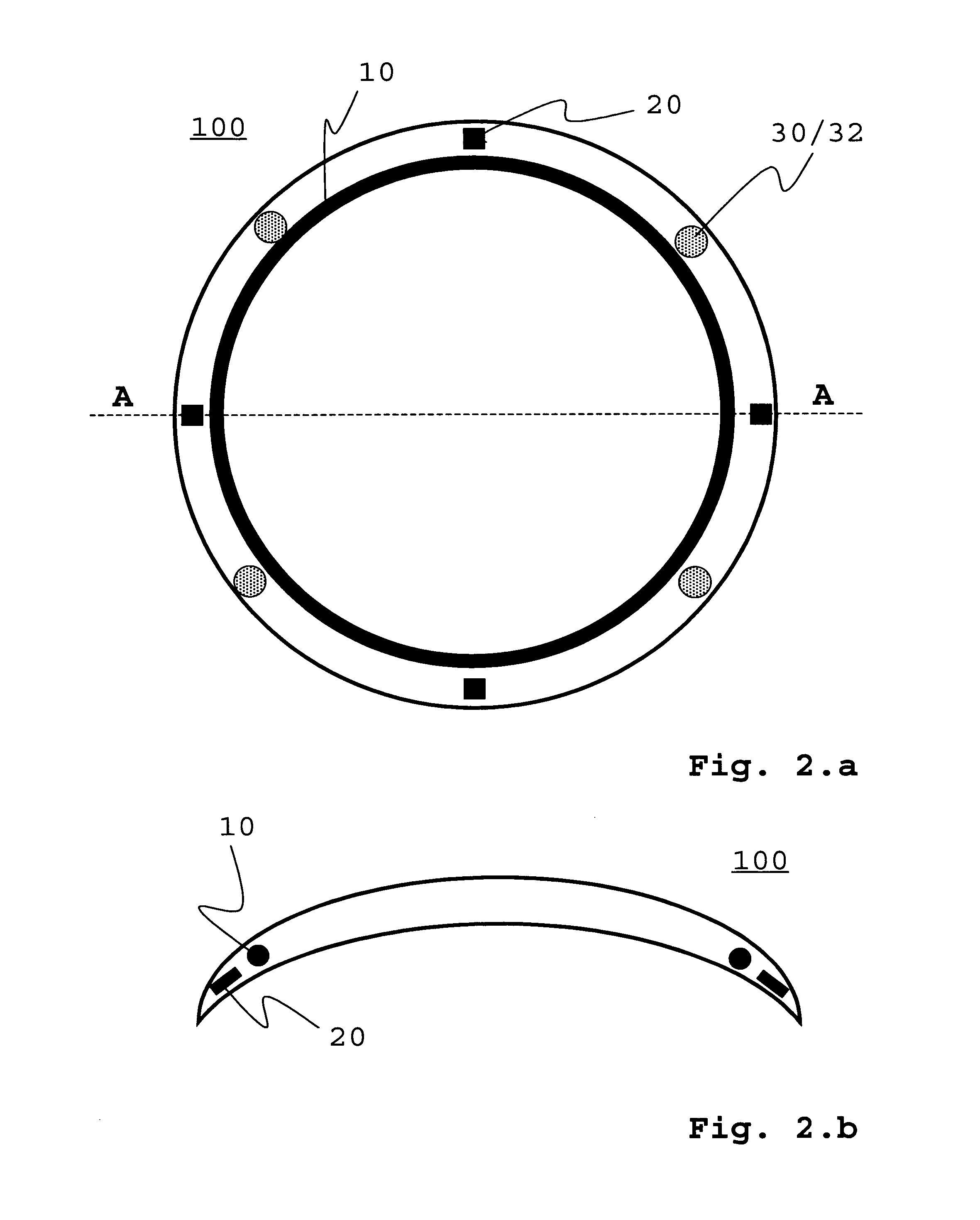
[0020]the present application claims a lens, especially with variable refraction power, comprising the following components:[0021]means for adaptation of the refraction power, especially by a shift of the lens curvature, as reaction to a control signal,[0022]at least one position locator,[0023]means for detection of a relative position of the position locator with respect to at least another position locator which is arranged on another lens, in particular such that an eye orientation is determinable or determined from the detected relative position of the position locator with respect to the other position locator,[0024]means for generation of a control signal in order to adapt the refraction power of the lens to the detected relative position, in particular such that a required refraction power or accommodation for the determined eye orientation is provided or can be provided, and[0025]at least one device for power supply of at least one part of the components of the lens.

[0026]Al...

second embodiment

[0058]Furthermore, the means for adaptation of the refraction power are embodied to a change of the refractive index of the lens. The change of the refractive index is preferably achieved essentially without changing the curvature of the lens. According to a possible variant, so-called electro-optical materials effect this change. The refractive index of such electro-optical materials can be influenced for example by an electric field, by a magnetic field and / or by an electromagnetic field. A defined refractive index distribution within the lens can thus be adjusted. The electro-optical material can be provided for example as electro-optical polymer. Changing the density of a compressive fluid provides another possibility for the change of the refractive index.

[0059]The adaptation of the refraction power results as a reaction to the control signal. The control signal comprises information concerning the necessary refraction power, as for example the lens curvature. The control sign...

third embodiment

[0084]FIGS. 3.a and 3.b schematically show exemplary the lens according to the invention in a top view and in a sectional view.

[0085]FIGS. 4.a and 4.b schematically depict exemplary a forth embodiment of the lens according to the invention in a top view and in a sectional view.


PUM


Abstract

The present invention comprises a lens with variable refraction power as well as an optical system for the use as, preferably accommodating, visual aid. The lens is designed as an intraocular lens or as a contact lens. The general idea of the invention is to determine the accommodation requirement from the position of the eyes relative to one another. This is possible, since the accommodation requirement and the eyes' motor activity are closely related. According to a first embodiment, the present invention claims a lens with variable refraction power, which possesses the following components: means for adaptation of the refraction power, especially by a change of the lens' curvature as a reaction to a control signal; at least one position locator; means for detection of the relative position of the position locator to at least another position locator arranged on another lens; means for generation of the control signal for adaptation of the refraction power of the lens to the detected relative position and at least one device for power supply for at least parts of the components of the lens.

Description

CROSS REFERENCE TO RELATED APPLICATIONS[0001]This application is a National Stage of International Application No. PCT / EP2010 / 002986, filed on May 15, 2010, which claims priority to German Application No. 10 2009 021 699.5 filed May 17, 2009, German Application No. 10 2009 040 933.5 filed Sep. 11, 2009, and U.S. Provisional Application No. 61 / 284,863 filed Dec. 28, 2009. The content of the prior applications are incorporated herein by reference in their entirety.DESCRIPTION OF THE INVENTION[0002]The present invention concerns a visual aid for the eye for reinstating eye-accommodability, a process for the reinstatement of the eye-accommodability as well as a process for production of such a visual aid.BACKGROUND OF THE INVENTION[0003]In the human eye, the lens is embedded behind pupil and iris within a notch or recess of the vitreous body. The function of the lens is to adapt the eye from close vision to far vision and vice versa. For example, while reading a book, the eye has to be ...

Claims


Application Information

Patent Timeline
Patent Type & Authority Patents(United States)
IPC IPC(8): G02C7/04
CPCA61F2/1613A61F2/1624G02C7/083G02C7/04A61F2/1635A61F2/1627G02C7/081H05K1/0284
Inventor BINDER, HELMUT
Owner BINDER HELMUT
Why Eureka
Try Eureka