Bus bar edge structure of electric junction box

a technology of electric junction box and end structure, which is applied in the direction of connection contact material, connection device connection, printed circuit, etc., can solve the problems of bad workability of inserting the bus bar b>65/b>, and achieve the effect of preventing electric wire damage, improving reliability of electrical connection of the electric junction box, and increasing assembly work of the bus bar

Active Publication Date: 2014-02-04
YAZAKI CORP
View PDF12 Cites 3 Cited by
  • Summary
  • Abstract
  • Description
  • Claims
  • Application Information

AI Technical Summary

Benefits of technology

[0015]According to the present invention of the first aspect, even if the electric wire is entered into a space crossed to the bus bar-receiving gap of the junction block main body, the projection piece of the bus bar prevents the entry of the electric wire. As a result, contact between the edge of the bus bar and the electric wire and damage of the electric wire can be prevented. Thus, reliability of electrically connection of the electric junction box can be improved. Furthermore, when the bus bar is pushed and assembled in the bus bar-receiving gap of the junction block main body, assembly work of the bus bar can be increased by pushing the projection piece of the bus bar.
[0016]According to the present invention of the second aspect, since the bus bar can be pressed into the bus bar-receiving gap of the junction block main body by pushing the projection piece with a hand, assembly work for attaching the bus bar in the electric junction box can be improved.
[0017]According to the present invention of the third aspect, the projection piece can securely prevent the electric wire from entering into the space including the longitudinal groove and the working space and then interfering with the bus bar edge interfering with the edge of the bus bar.
[0018]According to the present invention of the fourth aspect, even if the electric wire is arranged outside of the projection piece, the electric wire abuts on the partition ribs arranged in both sides of the projection piece. Thereby, contact between the electric wire and the bus bar edge can be prevented.
[0019]According to the present invention of the fifth aspect, even if a long bus bar is provided, the bus bar can be smoothly and firmly inserted into the bus bar-receiving gap by pressing two points, that is the projection piece and the folded connection. Furthermore, assembly work for attaching the bus bar in the electric junction box can be improved.

Problems solved by technology

As a result, workability for inserting the bus bar 65 is bad.

Method used


Image

  • Bus bar edge structure of electric junction box
  • Bus bar edge structure of electric junction box
  • Bus bar edge structure of electric junction box

Examples


Embodiment Construction

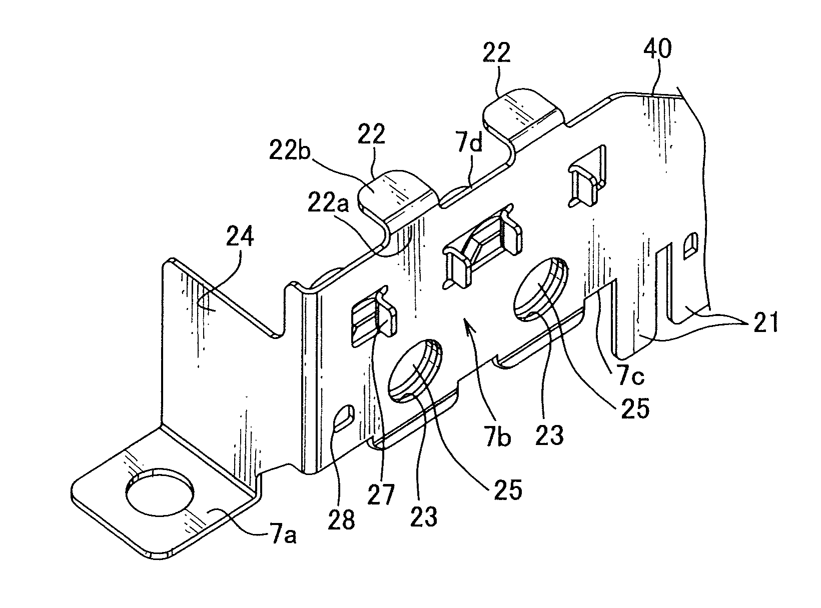
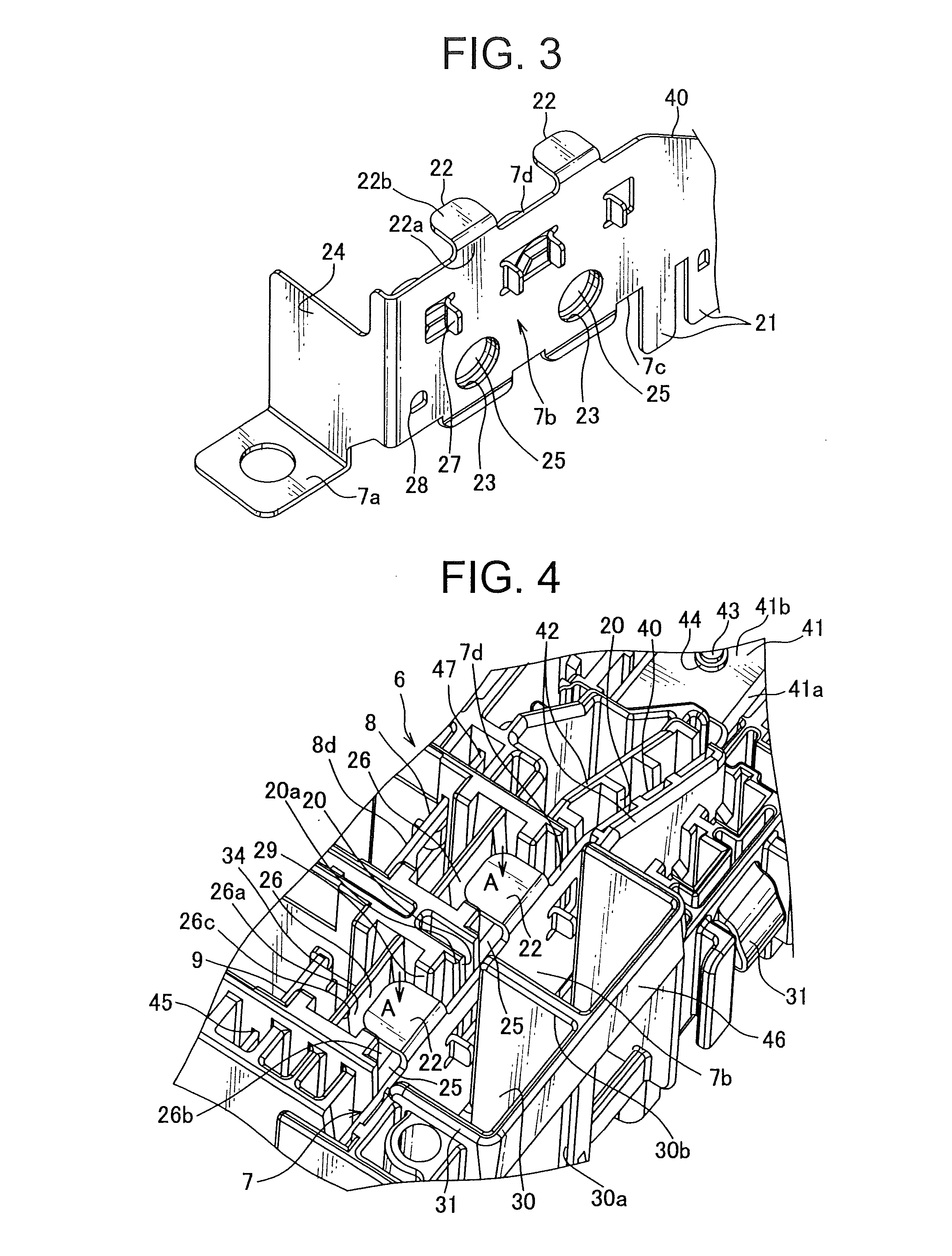
[0029]FIGS. 1 to 7 show a bus bar edge structure of an electric junction box according to an embodiment of the present invention. The bus bare edge structure may be referred to as a bus bar attaching structure.

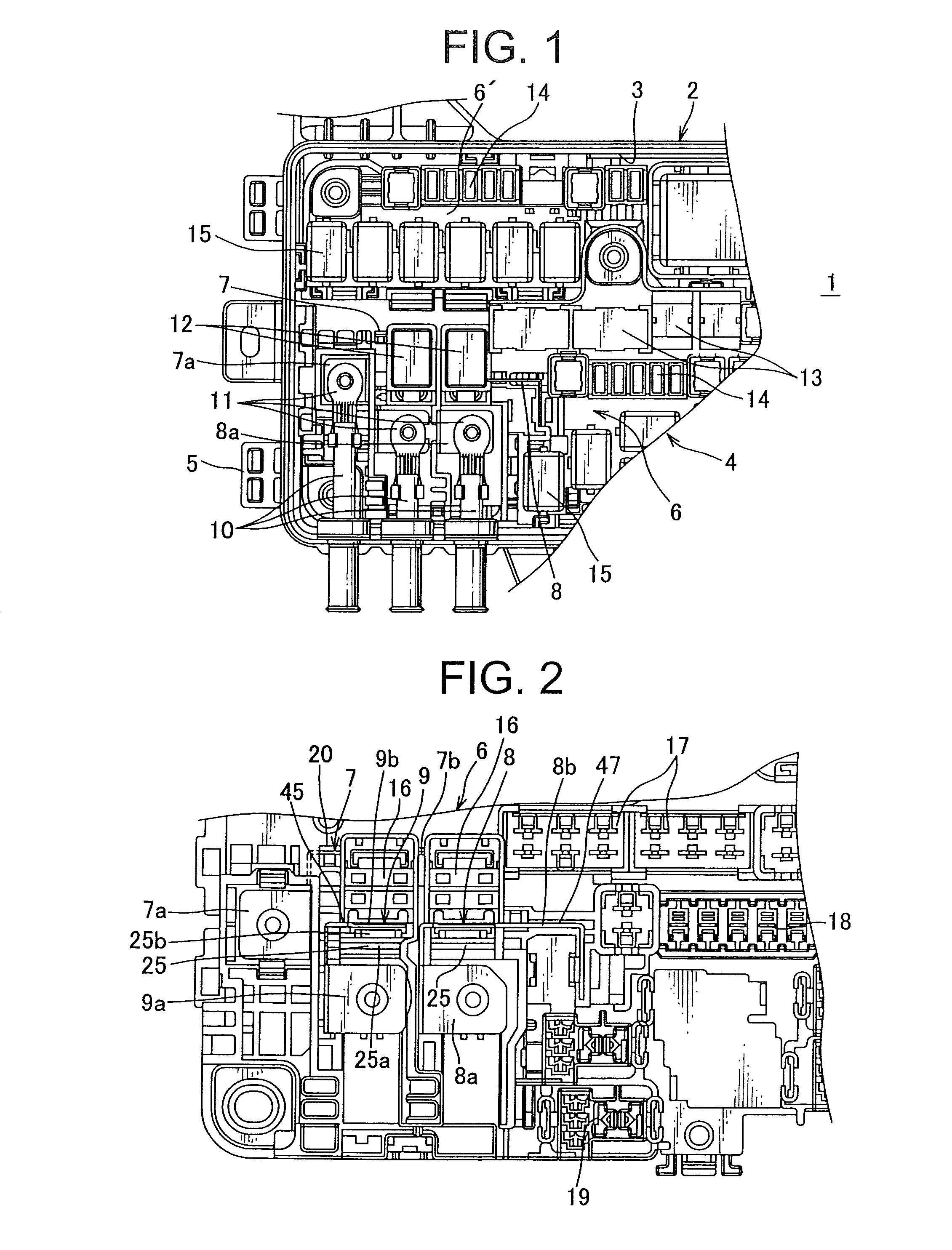
[0030]As shown in FIG. 1, the electric junction box 1 includes a lower cover 2, a junction block 4, and an upper cover not shown. The lower cover 2 is an electric junction box main body, has a bottom portion, and is made of insulating resin. The junction block 4 is attached to the lower cover 2 from an upper opening 3 of the lower cover 2 with a state mounted on a tray not shown. The upper cover covers the upper opening 3 of the lower cover 2, and is fixed in a hinge 5 arranged on either side of the lower cover 2.

[0031]The junction block 4 includes a junction block main body 6 made of insulating resin, at least three bus bars 7, 8, 9 (see FIG. 2) received in the junction block main body 6, power-supply terminals 11 with an thick electric wire 10, and electric components mounte...


PUM


Abstract

A bus bar edge structure of an electric junction box having a junction block main body, a bus bar-receiving gap arranged on the junction block main body, and a space communicating with the bus bar-receiving gap and arranged in a thickness direction of the bus bar includes a projection piece projecting from an edge of the bus bar at an opening side of the space in the thickness direction of the bus bar. An electric wire led from the junction block main body is guided to the projection piece so as to prevent interference with the edge of the bus bar. The projection piece functions as a press-operating portion configured to insert the bus bar into the bus bar-receiving gap. The projection piece is positioned in an opening of a longitudinal groove arranged in the space so as to prevent the electric wire from entering into the opening.

Description

[0001]The priority application Number Japan Patent Application No. 2011-165207 upon which this patent application is based is hereby incorporated by reference.TECHNICAL FIELD[0002]The present invention relates to a bus bar end structure of an electric junction box so as to prevent contact between an edge of a bus bar of an electric junction box and an electric wire.BACKGROUND OF THE INVENTION[0003]Conventionally, various bus bar attaching structures of an electric junction box are provided so as to attach a bus bar made of an electrical conduction metal plate in the electric junction box mounted on a vehicle and so on.[0004]For example, in the Patent Document 1, as shown in FIG. 8, a box main boy (junction box main body) 62, which is made of insulating resin, of a fuse box (electric junction box) 61 includes a bus bar receiving portion 63 and a terminal receiving portion 64 arranged parallel to the bus bar receiving portion 63. The bus bar receiving portion 63 has an outer wall 63a,...

Claims


Application Information

Patent Timeline
Patent Type & Authority Patents(United States)
IPC IPC(8): H01R12/00
CPCH01R9/2458H05K7/026H01R9/226
Inventor I, SUNSOKUKAKIMI, TAKAAKI
Owner YAZAKI CORP
Why Eureka
Try Eureka